Metro traction inverter chopper power unit

A wave power and inverter technology, applied in the field of subway traction inverter chopper power unit, can solve the problems of unguaranteed reliability, cumbersome and time-consuming, and increased electrical gap, so as to save operating costs, improve maintenance efficiency, and replace and maintain convenient effect

Active Publication Date: 2016-08-31
CRRC YONGJI ELECTRIC CO LTD
View PDF5 Cites 0 Cited by
  • Summary
  • Abstract
  • Description
  • Claims
  • Application Information

AI Technical Summary

Problems solved by technology

[0004] Existing technology 1: 1) Common copper bars are used to connect the components of the main circuit of the traction inverter power unit, and the IGBT absorbing circuit is complicated; 2) The driving board is directly installed on the IGBT or independently installed on the upper layer of the IGBT
[0005] The disadvantages of prior art 1 are: 1) The circuit is connected by ordinary copper bars, and the electrical gap increases, resulting in an increase in the volume of the entire power unit and an increase in the space occupied by the converter; in addition, the stray inductance of ordinary copper bars is large, requiring additional A lot of absorption circuits are installed, resulting in complex circuit structure and more accessories, which reduces the reliability of the entire power unit
2) The driver board is directly installed on the IGBT or independently installed on the upper layer of the IGBT, which makes it inconvenient to maintain the power unit. When replacing the IGBT device or the driver board, there are many accessories that need to be removed, which is not only cumbersome and time-consuming, but also the reliability after maintenance. Not guaranteed
[0007] The disadvantage of the second prior art is: the two are independent, and two sets of radiators are required, which takes up a lot of space in the vehicle

Method used


Image

  • Metro traction inverter chopper power unit
  • Metro traction inverter chopper power unit
  • Metro traction inverter chopper power unit

Examples


Embodiment Construction

[0024] The present invention will be further described below in conjunction with accompanying drawing:

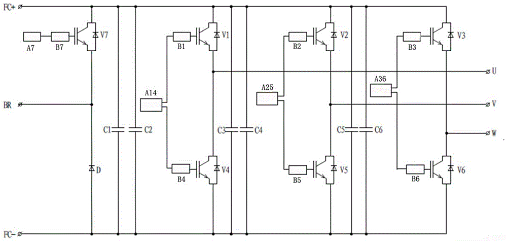
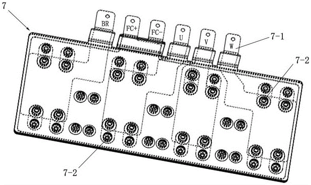
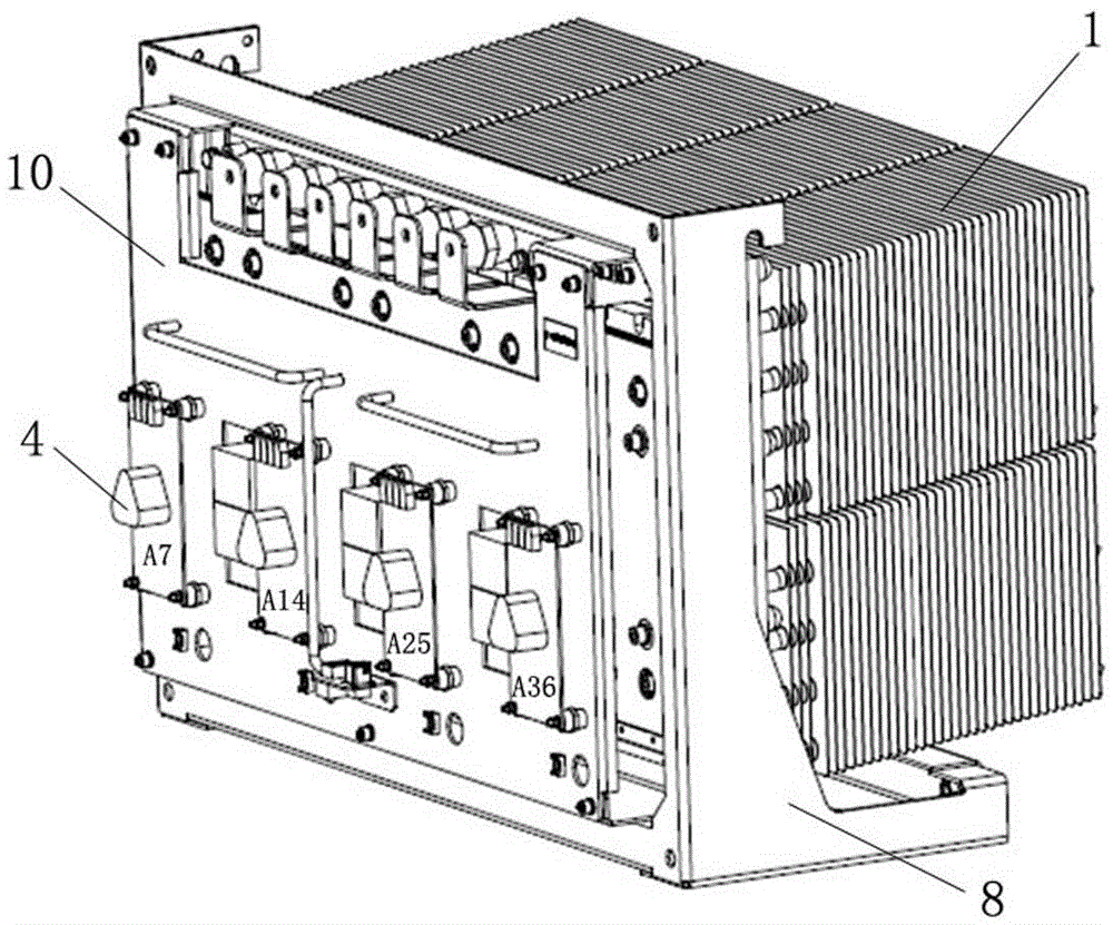
[0025] Such as Figure 1 to Figure 5 As shown, a subway traction inverter chopper power unit includes a radiator 1, an IGBT device 2, an IGBT configuration board 3, an IGBT driver board 4, a diode device 5, an absorbing capacitor 6 and a composite busbar 7; A support frame 8 is installed, and six insulators 9 are arranged on the support frame 8; the number of IGBT devices 2 is seven, the number of diode devices 5 is one, and the seven IGBT devices 2 and one diode device 5 are pasted in two rows Attached to the heat sink 1, one row is four IGBT devices 2, the other row is a diode device 5 and three IGBT devices 2; the number of IGBT configuration boards 3 is seven, and the seven IGBT configuration boards 3 are installed On the corresponding IGBT device 2; the composite busbar 7 is covered and attached to seven IGBT devices 2 and one diode device 5. The composite busbar 7 is...


PUM


Abstract

The invention relates to a metro traction inverter chopper power unit, which is composed of a radiator, seven IGBT devices, seven IGBT configuration boards, four IGBT drive boards, diode devices, six absorption capacitors and composite busbars. The invention concentrates the brake chopper circuit and the inverter circuit on one power unit, shares a set of heat pipe radiators, and reduces the space occupied by the vehicle. The main circuit busbar adopts composite busbar, which reduces the electrical gap between the busbars, between the busbar and the supporting frame, and absorbs circuit accessories, reduces the volume of the power unit, and increases the reliability. The stacked structure is adopted, and the IBGT drive board components are uniformly installed on the outside of the module, which is convenient for replacement and maintenance. The invention reduces the volume of the entire power unit, saves space, improves maintenance efficiency, further improves the utilization rate of subway trains, and saves operating costs.

Description

technical field [0001] The invention relates to the technical field of subway traction systems, in particular to a subway traction inverter chopper power unit. Background technique [0002] With the rapid development of high-power semiconductor device IGBT manufacturing technology and drive technology, as the core component of the traction converter in the subway traction system, the traction inverter power unit has also been developed rapidly, towards high-frequency miniaturization and high reliability. direction development. [0003] The input of the traction inverter chopper power unit comes from the DC voltage of the subway power grid. The IGBT is selected as the switching device, and the purpose of outputting the three-phase AC voltage is achieved through the inverter method, and then the traction motor of the subway is controlled to realize the traction function. At the same time, with the cooperation of the traction converter control system, the brake chopper functio...

Claims


Application Information

Patent Timeline
Patent Type & Authority Patents(China)
IPC IPC(8): H02M7/00H05K7/20
Inventor 刘革莉冷丽英杨春宇陈宏赵一洁
Owner CRRC YONGJI ELECTRIC CO LTD
Why Eureka
Try Eureka