Monolithic ceramic capacitor

a monolithic ceramic capacitor and monolithic ceramic technology, applied in the direction of capacitors, fixed capacitor details, fixed capacitors, etc., can solve the problems of unstable operation of the circuit to be driven, oscillation, and often generated noise primarily including harmonic wave components, so as to improve the mountability of the lw-reverse-type monolithic ceramic capacitor and reduce the reliability of the capacitor

Active Publication Date: 2010-10-05
MURATA MFG CO LTD
View PDF26 Cites 29 Cited by
  • Summary
  • Abstract
  • Description
  • Claims
  • Application Information

AI Technical Summary

Benefits of technology

[0021]To overcome the problems described above, preferred embodiments of the present invention provide an LW-reverse-type monolithic ceramic capacitor including external terminal electrodes each including a resistance component, the structure being suitable for improving the mountability of the LW-reverse-type monolithic ceramic capacitor without decreasing the reliability thereof.
[0025]According to a preferred embodiment of the present invention, since the second layer is arranged such that the edge of the wrap-around portion of the first layer remains exposed, the dimensions of the wrap-around portion of the external terminal electrode are defined by the first layer. As a result, the dimensions of the wrap-around portion of the external terminal electrode are consistent. Thus, satisfactory mountability of the monolithic ceramic capacitor can be reliably achieved.
[0026]Furthermore, since the second layer is arranged such that the edge of the wrap-around portion of the first layer remains exposed, a plating solution or moisture may easily intrude from the edge of the wrap-around portion of the first layer. However, the distance between the edge of the wrap-around portion and a capacitance-forming portion of the internal electrodes is sufficiently large, and thus, the plating solution or moisture does not easily reach the capacitance-forming portion. Therefore, the reliability of the monolithic ceramic capacitor is not significantly decreased.
[0027]In addition, since the second layer does not completely cover the first layer and is formed such that the edge of the wrap-around portion remains exposed, this structure enables a decrease in the thickness of the external terminal electrode at the wrap-around portion. Consequently, the size of the monolithic ceramic capacitor can be reduced accordingly.

Problems solved by technology

In a power supply circuit, when a voltage variation in a power supply line is increased by an impedance that is present in the power supply line or a ground, the operation of circuits to be driven becomes unstable, interference between the circuits occurs due to the power supply circuit, or oscillation occurs.
Accordingly, noise that primarily includes harmonic wave components is often generated.
However, it is known that when the ESR of a capacitor is excessively decreased, a mismatch of impedance occurs in a circuit and a damped oscillation called “ringing” in which the rising of a signal waveform deforms easily occurs.
The ringing may cause a malfunction of an IC because of disordered signals.
In addition, when the ESR of a capacitor is excessively decreased, the impedance-frequency characteristic of the capacitor becomes excessively steep near the resonance frequency.
More specifically, the valley of the impedance curve becomes excessively deep.
Consequently, it may be difficult to absorb noise over a wide frequency range.
However, the techniques described in documents '983 and '258 have problems to be solved as described below.
Consequently, a plating solution or moisture easily intrudes into the film, thus causing a problem of reduced reliability.
Accordingly, it is difficult to reduce the size of the monolithic ceramic capacitor.
This problem tends to be particularly troublesome in LW-reverse-type monolithic ceramic capacitors, which have a large area of external terminal electrodes.
Therefore, it is difficult to stabilize the dimensions of the wrap-around portion.
If the dimensions of the wrap-around portion vary, the mountability may be adversely affected.

Method used


Image

  • Monolithic ceramic capacitor
  • Monolithic ceramic capacitor
  • Monolithic ceramic capacitor

Examples


Embodiment Construction

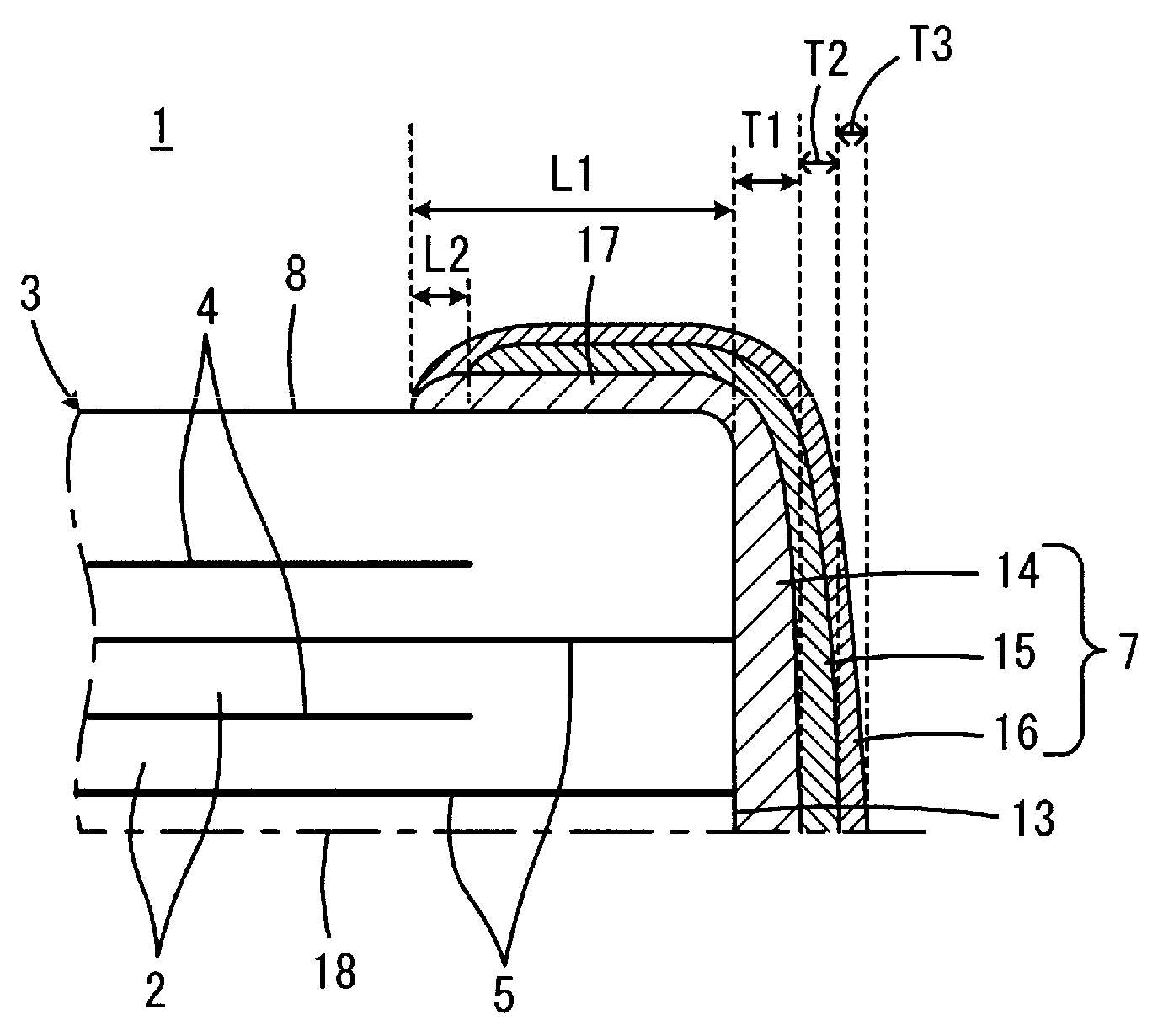
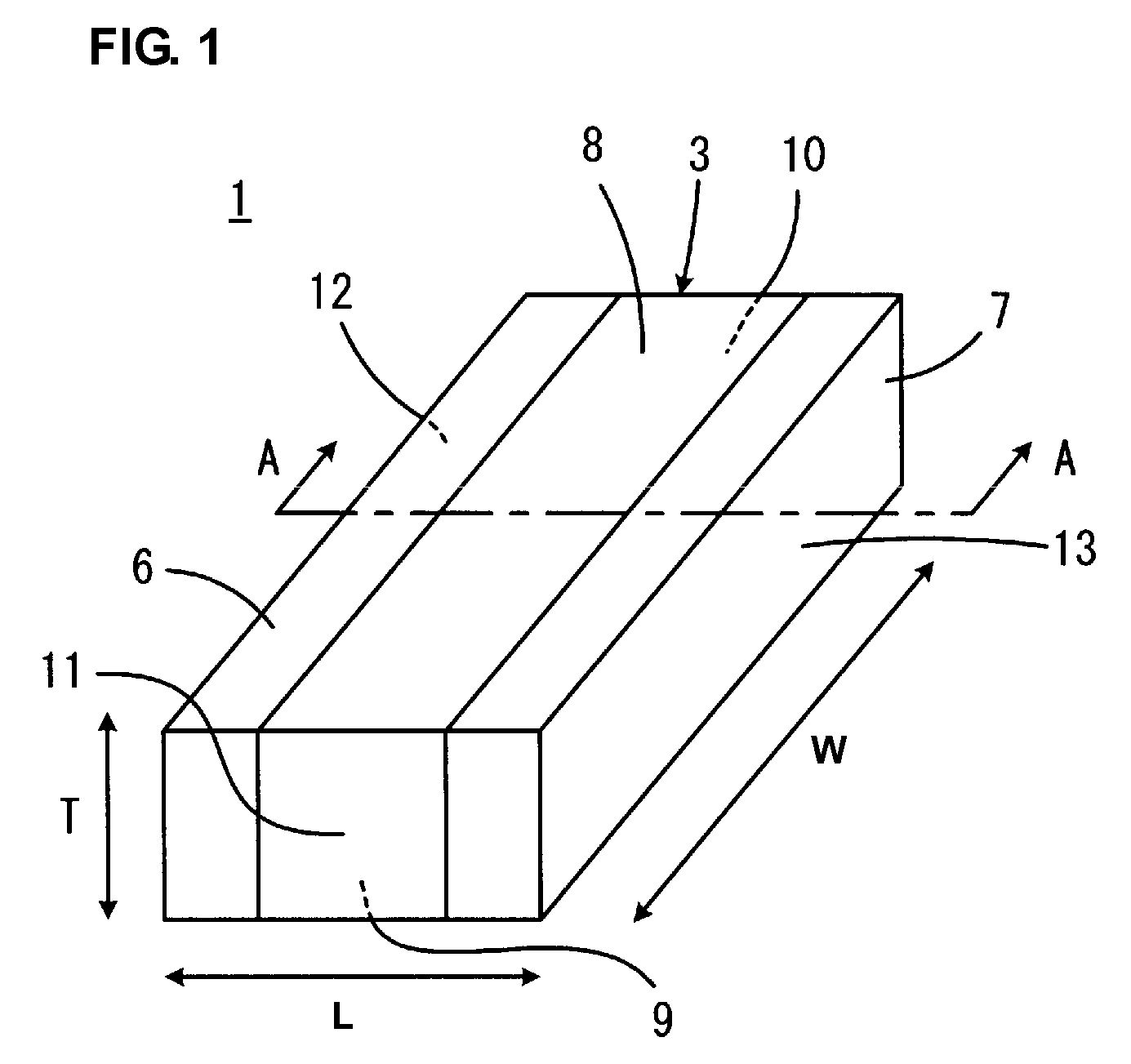
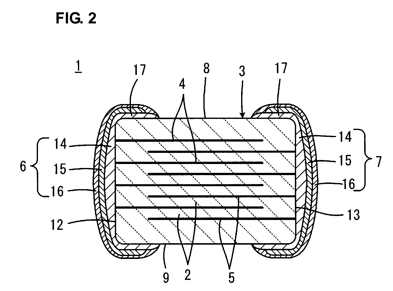
[0036]FIG. 1 is a perspective view showing a monolithic ceramic capacitor 1 according to a preferred embodiment of the present invention. FIG. 2 is a cross-sectional view of the monolithic ceramic capacitor 1 taken along line A-A in FIG. 1.

[0037]The monolithic ceramic capacitor 1 includes a capacitor main body 3 including a plurality of laminated ceramic layers 2, at least one pair of internal electrodes 4 and 5 provided inside the capacitor main body 3, a first external terminal electrode 6, and a second external terminal electrode 7. The first external terminal electrode 6 and the second external terminal electrode 7 are provided on outer surfaces of the capacitor main body 3 so as to face each other.

[0038]Each of the ceramic layers 2 in the capacitor main body 3 is preferably made of, for example, a dielectric ceramic including, as a main component, BaTiO3, CaTiO3, SrTiO3, CaZrO3, or other suitable material. An auxiliary component such as a manganese (Mn) compound, an iron (Fe) c...


PUM

PropertyMeasurementUnit
thicknessaaaaaaaaaa
thickness T3aaaaaaaaaa

Abstract

In an LW-reverse-type monolithic ceramic capacitor including external terminal electrodes each including a resistance component, internal electrodes include nickel or a nickel alloy, and the external terminal electrodes each include a first layer, a second layer provided on the first layer, and a third layer provided on the second layer. The first layer has a wrap-around portion extending from an end surface to principal surfaces and side surfaces of a capacitor main body, and contains a glass component and a compound oxide that reacts with Ni or the Ni alloy. The second layer covers the first layer such that the edge of the wrap-around portion of the first layer remains exposed, and contains a metal. The third layer covers the edge of the wrap-around portion of the first layer and the second layer, and is formed by plating.

Description

BACKGROUND OF THE INVENTION[0001]1. Field of the Invention[0002]The present invention relates to a monolithic ceramic capacitor, and in particular, to an LW-reverse-type monolithic ceramic capacitor including external terminal electrodes each including a resistance component.[0003]2. Description of the Related Art[0004]In a power supply circuit, when a voltage variation in a power supply line is increased by an impedance that is present in the power supply line or a ground, the operation of circuits to be driven becomes unstable, interference between the circuits occurs due to the power supply circuit, or oscillation occurs. Consequently, a decoupling capacitor is usually connected between the power supply line and the ground. The decoupling capacitor decreases the impedance between the power supply line and the ground, thereby suppressing the variation in the power supply voltage and interference between the circuits.[0005]Recently, in communication equipment such as a cell phone a...

Claims


Application Information

Patent Timeline
Patent Type & Authority Patents(United States)
IPC IPC(8): H01G4/228H01G4/005
CPCH01G4/232H01G4/2325
Inventor ITAMURA, HIROTOTANIGUCHI, MASAAKIKAWAGUCHI, YOSHIO
Owner MURATA MFG CO LTD
Why Eureka
Try Eureka