Driving apparatus

a technology of driving apparatus and motor shaft, which is applied in the direction of printing mechanism, spacing mechanism, printing, etc., can solve the problems of reducing the operation affecting the operation efficiency of the printer, and causing noise, etc., to achieve the effect of reducing the operation efficiency and impact for

Inactive Publication Date: 2010-10-12
BROTHER KOGYO KK
View PDF15 Cites 7 Cited by
  • Summary
  • Abstract
  • Description
  • Claims
  • Application Information

AI Technical Summary

Benefits of technology

[0012]However, in the above-described home-position detecting operation, the carriage needs to be impacted on the side frame of the printer, and the impaction may damage the components of the printer and / or may produce noise. To solve this problem, the conventional printer is adapted to move, in the home-position detecting operation, the carriage at a lowered velocity, or employs a sensor that is provided at a detection position before the home position and detects that the carriage has reached the detection position. In the latter case, when the carriage reaches the detection position, then the carriage is moved at a lowered velocity. Thus, in each case, the impact force produced when the carriage impacts on the side frame is reduced.
[0013]However, in the above-indicated former case, the carriage is moved at the lowered velocity till it impacts on the side frame, irrespective of where the movement of the carriage is started. Therefore, the home-position detecting operation takes a long time, which leads to lowering the operation efficiency of the printer, such as the efficiency of the image recording operation.
[0014]In the above-indicated latter case, the increase of the time taken by the home-position detecting operation can be minimized, but the sensor is additionally needed. In addition, the printer needs to be modified to be able to control the motor operating amount based on the result detected by the sensor, which leads to increasing the size and production cost of the printer.
[0015]It is therefore an object of the present invention to solve at least one of the above-indicated problems. It is another object of the present invention to provide a driving apparatus which includes a linear encoder that detects a position of an object and accurately drives or moves the object based on an output of the encoder, and which additionally includes a stopper that engages the object and thereby stops a further movement of the object, without needing to complicate a construction of the driving apparatus or lower an operation efficiency thereof while an impact force produced when the object impacts on the stopper is reduced. It is another object of the present invention to provide a driving apparatus which includes a linear encoder and a stopper and which carries out a reference-position detecting operation to detect a reference position of an object based on a current position of the object at the time when the object being moved is impacted on, and stopped by, the stopper.
[0017]In this driving apparatus, the second scale portion of the linear scale has the plurality of second detectable portions including at least one pair of adjacent second detectable portions which are distant from each other by the first predetermined distance smaller than the first predetermined pitch at which the plurality of first detectable portions of the first scale portion are provided. That is, a resolution of the second scale portion is higher than a resolution of the first scale portion. Thus, the object can be moved a lowered velocity before the object impacts on the stopper. Therefore, the object can be accurately moved based on the detection signals of the encoder, without needing to complicate a construction of the driving apparatus or lower an operation efficiency thereof, while an impact force produced when the object impacts on the stopper is reduced.
[0022]This driving apparatus need not modify a software arrangement such that when the reference position of the object is detected, the object is moved at a lowed velocity from a start of the operation, or need not modify a hardware construction, e.g., employ a sensor, so as to detect that the object has reached a position before the reference position. Thus, the present driving apparatus can determine the reference position of the object, without needing to complicate the construction of the driving apparatus or lower the operation efficiency thereof, while the impact force produced when the object impacts on the stopper is reduced.

Problems solved by technology

However, in the above-described home-position detecting operation, the carriage needs to be impacted on the side frame of the printer, and the impaction may damage the components of the printer and / or may produce noise.
Therefore, the home-position detecting operation takes a long time, which leads to lowering the operation efficiency of the printer, such as the efficiency of the image recording operation.
In addition, the printer needs to be modified to be able to control the motor operating amount based on the result detected by the sensor, which leads to increasing the size and production cost of the printer.

Method used


Image

  • Driving apparatus
  • Driving apparatus
  • Driving apparatus

Examples


first embodiment

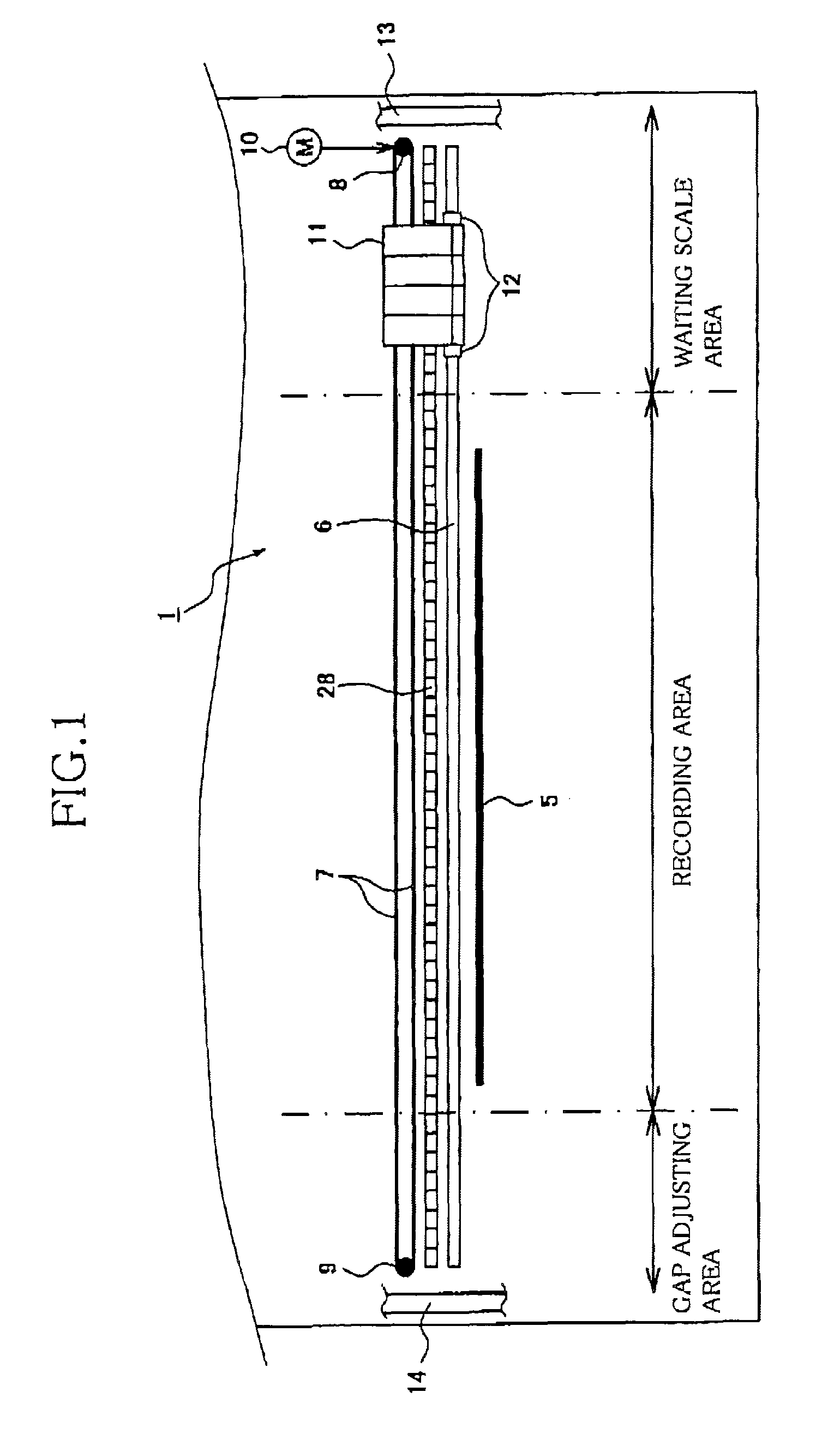
[0044]FIG. 1 schematically shows a construction of a carriage driving apparatus 1, employed by an ink-jet printer (hereinafter, simply referred to as the printer), to which the present invention is applied.

[0045]As shown in FIG. 1, the carriage driving apparatus 1 employs a guide bar 6 extending in a widthwise direction of a recording sheet 5 that is fed by a feeding roller, not shown. The guide bar 6 supports a carriage 12 on which a head unit 11 is mounted. The head unit 11 is supplied with four sorts of inks from four ink cartridges, not shown, and includes a recording head, not shown, that has four groups of nozzles for ejecting droplets of the four inks toward the recording sheet 5 and thereby recording a full-color image on the same 5.

[0046]The carriage 12 is connected to an endless belt 7 extending along the guide bar 6, and the endless belt 7 is wound on a drive pulley 8 connected to a carriage motor 10 provided in the vicinity of one of opposite ends of the guide bar 6 and ...

second embodiment

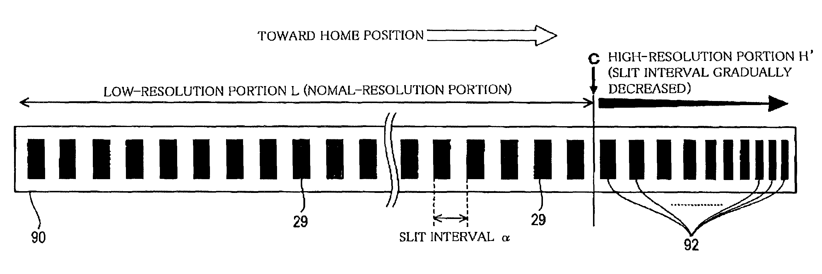
[0107]Next, a second embodiment of the present invention will be described by reference to FIGS. 13 and 14. The second embodiment also relates to a carriage driving apparatus of an ink-jet printer, and differs from the carriage driving apparatus 1 as the first embodiment, only in that though the slit intervals β of the high-resolution scale portion H of the linear scale 28 employed in the first embodiment are constant, intervals of encoder slits 92 of a high-resolution scale portion H′ of a linear scale 90 of a linear encoder employed in the second embodiment gradually decrease in a direction toward the origin (i.e., home position) of the carriage 12. The same reference numerals as used in the first embodiment are used to designate the corresponding elements or parts of the second embodiment, and the description thereof is omitted. Hereinafter, only differences of the first and second embodiments will be described.

[0108]As is apparent from the comparison of the linear scale 90, show...

third embodiment

[0113]Next, a third embodiment of the present invention will be described by reference to FIG. 15. The third embodiment also relates to a carriage driving apparatus of an ink-jet printer, and differs from the carriage driving apparatus 1 as the first embodiment, only with respect to a manner of judging whether the carriage 12 has impacted on the side frame 13. In the first embodiment, the home-position detecting operation is carried out according to the flow chart shown in FIG. 12, so as to judge whether the carriage 12 has passed through the resolution-change point C, based on the difference values, diff_v, obtained by the difference obtaining portion 71, and likewise judge, based on the difference values, diff_v, whether the carriage 12 has impacted on the side frame 13 after having passed through the resolution-change point C. However, in the third embodiment, the carriage driving apparatus judges whether the carriage 12 has impacted on the side frame 13, by judging whether the c...


PUM


Abstract

A driving apparatus, including a driving device which moves an object along a predetermined path; a linear encoder including a linear scale and a detector one of which is moved relatively to the other when the object is moved along the predetermined path; a control device which controls, based on an output of the detector, the driving device to move the object along the predetermined path; and at least one stopper which engages, when the object is moved along the predetermined path, the object and thereby stops a further movement of the object. The linear scale includes at least one first scale portion having a plurality of first detectable portions provided at a predetermined pitch, and at least one second scale portion having a plurality of second detectable portions including at least one pair of adjacent second detectable portions which are adjacent to each other and which are distant from each other by a predetermined distance smaller than the predetermined pitch. The first scale portion and the second scale portion are located relative to each other such that when the object is moved toward the stopper, the detector first detects the first detectable portions and then detects the second detectable portions, while sequentially outputting a plurality of detection signals, and the control device controls, based on the detection signals, the driving device to move the object along the predetermined path.

Description

[0001]The present application is based on Japanese Patent Application No. 2005-159966 filed on May 31, 2005, the contents of which are incorporated herein by reference.BACKGROUND OF THE INVENTION[0002]1. Field of the Invention[0003]The present invention relates to a driving apparatus including a driving device that drives or moves an object such as a carriage, a linear encoder, and a control device or portion that controls, based on an output of the linear encoder the driving device to move the object.[0004]2. Discussion of Related Art[0005]There has been known a linear driving apparatus which includes a linear motor, or a combination of a rotary motor and a converting device that converts a rotary driving force of the rotary motor into a linear motion, and which linearly drives or moves an object by utilizing the linear motion. Generally, this sort of linear driving apparatus performs a so-called feedback control in which a position or a velocity of the object is detected and the m...

Claims


Application Information

Patent Timeline
Patent Type & Authority Patents(United States)
IPC IPC(8): B41J23/00
CPCB41J19/202B41J29/393
Inventor AKIYAMA, SHIGEKI
Owner BROTHER KOGYO KK
Why Eureka
Try Eureka