Structure of LiAlO2 substrate having ZnO buffer layer

a technology of zinc oxide and substrate, applied in the direction of discharge tube luminescnet screen, polycrystalline material growth, crystal growth process, etc., can solve the problems of reducing the quality of the crystal interface, not as popular, and the device quality and lifetime is still not satisfying, so as to enhance the light emission efficiency of the photoelectric device, effectively eliminating the qcse, and eliminating the qcse

Inactive Publication Date: 2010-10-12
NAT SUN YAT SEN UNIV +1
View PDF3 Cites 2 Cited by
  • Summary
  • Abstract
  • Description
  • Claims
  • Application Information

AI Technical Summary

Benefits of technology

[0004]The main purpose of the present invention is to grow a non-polar ZnO layer on a LiAlO2 substrate for effectively eliminating a QCSE by the ZnO having the same direction as that of the LiAlO2 because of a structural similarity.
[0005]To achieve the above purpose, the present invention is a structure of a LiAlO2 substrate having a ZnO buffer layer, where a ZnO buffer layer is grown on a LiAlO2 substrate as a single crystalline thin film for effectively eliminating a QCSE by the ZnO having the same direction as that of the LiAlO2 because of a structural similarity so as to enhance a light emitting efficiency of a photoelectrical device made therewith. Accordingly, a novel structure of LiAlO2 substrate having a ZnO buffer layer is obtained.

Problems solved by technology

Although some gallium nitride (GaN) based blue-green light emitting devices gain some breakthroughs in recent years, qualities and lifetimes of the devices are still not satisfying.
Concerning a light emitting device using zinc oxide (ZnO), it is not as popular as one using GaN and even has the similar situation for not having a matching substrate.
Such a situation breaks the balance between lattices of the whole structure; and a mismatching as high as 13.6% is reached to down the quality of the crystal interface and to degrade the performance of the device made therewith.
Hence the prior arts do not fulfill all users' requests on actual use.

Method used


Image

  • Structure of LiAlO2 substrate having ZnO buffer layer
  • Structure of LiAlO2 substrate having ZnO buffer layer
  • Structure of LiAlO2 substrate having ZnO buffer layer

Examples


Embodiment Construction

[0010]The following description of the preferred embodiment is provided to understand the features and the structures of the present invention.

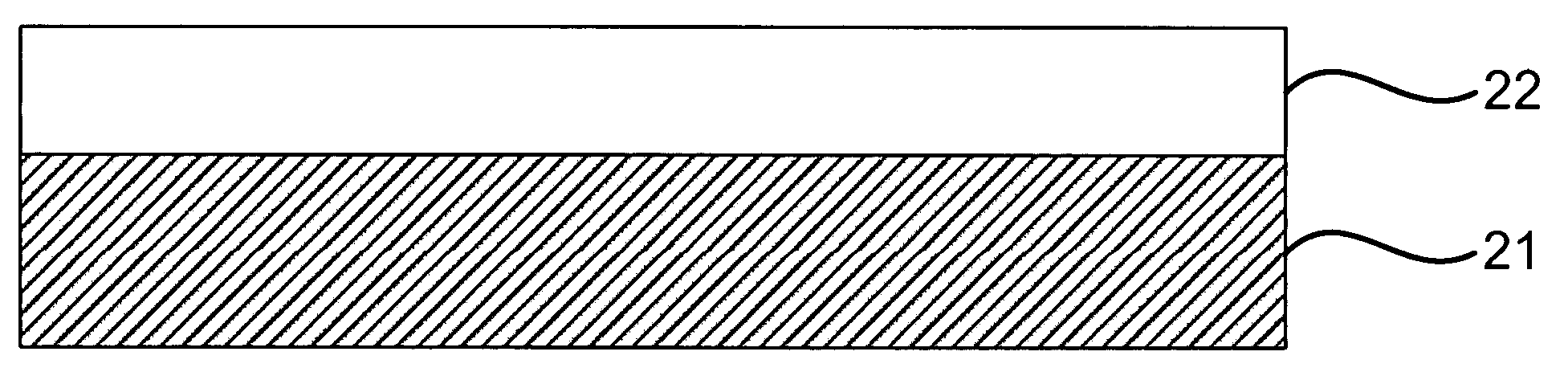
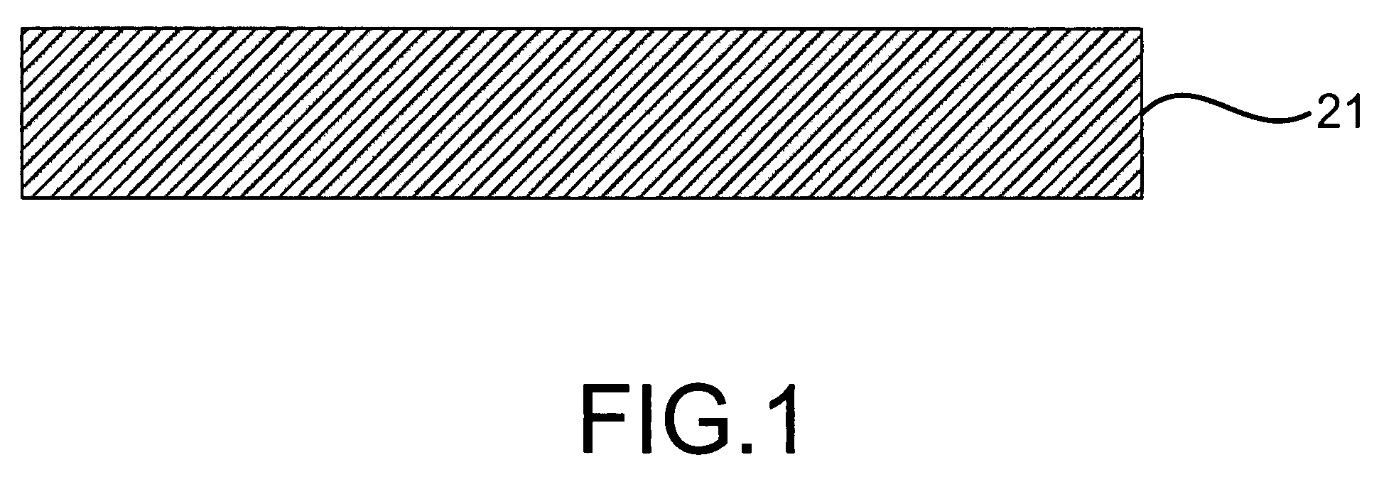
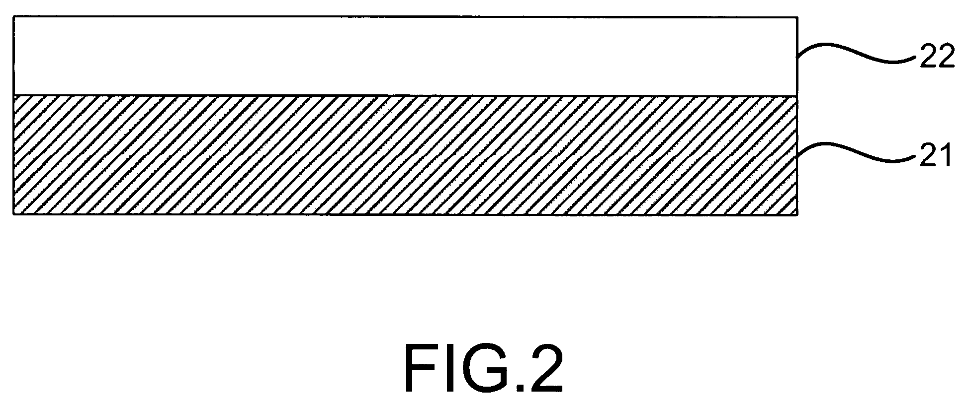
[0011]Please refer to FIG. 1 and FIG. 2, which are views showing a LiAlO2 substrate and a ZnO buffer layer of a preferred embodiment according to the present invention. As shown in the figures, the present invention is a structure of a lithium aluminum oxide (LiAlO2) substrate having a zinc oxide (ZnO) buffer layer, comprising a substrate made of lithium aluminum oxide (LiAlO2) 21 and a buffer layer made of zinc oxide (ZnO) 22, where a quantum confined stark effect (QCSE) is eliminated to enhance a light emitting efficiency of a photo electrical device made therewith.

[0012]The substrate made of LiAlO2 21 can be further a substrate made of sodium aluminum oxide (NaAlO2), lithium gallium oxide (LiGaO2), sodium silicon oxide (Na2SiO3), sodium zinc silicon oxide (Na2ZnSiO4), lithium silicon oxide (Li2SiO3), lithium zinc silicon oxide (Li2ZnSiO4),...


PUM

PropertyMeasurementUnit
structureaaaaaaaaaa
latticeaaaaaaaaaa
piezoelectricaaaaaaaaaa

Abstract

A lithium aluminum oxide (LiAlO2) substrate suitable for a zinc oxide (ZnO) buffer layer is found. The ZnO buffer layer is grown on the LiAlO2 substrate. Because the LiAlO2 substrate has a similar structure to that of the ZnO buffer layer, a quantum confined stark effect (QCSE) is effectively eliminated. And a photoelectrical device made with the present invention, like a light emitting diode, a piezoelectric material or a laser diode, thus obtains an enhanced light emitting efficiency.

Description

FIELD OF THE INVENTION[0001]The present invention relates to a substrate for a zinc oxide (ZnO) buffer layer; more particularly, relates to growing a non-polar ZnO layer on a lithium aluminum oxide (LiAlO2) substrate for effectively eliminating a quantum con fined stark effect (QCSE) by the ZnO having the same direction as that of the LiAlO2 because of a structural similarity.DESCRIPTION OF THE RELATED ARTS[0002]Light emitting devices, like a light emitting diode (LED), a laser diode (LD), etc., have wide applications and a big potential market. Although some gallium nitride (GaN) based blue-green light emitting devices gain some breakthroughs in recent years, qualities and lifetimes of the devices are still not satisfying. Such a situation mainly comes from the lacking of a matching substrate for GaN.[0003]Concerning a light emitting device using zinc oxide (ZnO), it is not as popular as one using GaN and even has the similar situation for not having a matching substrate. As shown ...

Claims


Application Information

Patent Timeline
Patent Type & Authority Patents(United States)
IPC IPC(8): H01L51/50B32B9/00H05B33/00B32B9/04
CPCC30B29/16C30B29/20H01L33/0066H01S2301/173
Inventor CHOU, MITCH M. C.WU, JIH-JENHSU, WEN-CHING
Owner NAT SUN YAT SEN UNIV
Why Eureka
Try Eureka