Current detection apparatus for a car power source

a technology for power sources and current detection equipment, applied in the direction of instruments, measurement using digital techniques, transportation and packaging, etc., can solve the problems of complex circuit structure and lower detection precision, and achieve the effect of high precision, lower detection precision and complex circuit structur

Inactive Publication Date: 2010-10-12
SANYO ELECTRIC CO LTD
View PDF8 Cites 1 Cited by
  • Summary
  • Abstract
  • Description
  • Claims
  • Application Information

AI Technical Summary

Benefits of technology

[0009]The apparatus of FIG. 2 can detect current with high precision by optimally adjusting the charging current range and the discharging current range via the gain of respective op-amps. However, since this apparatus detects charging current and discharging current by switching between dedicated op-amps, its circuit structure becomes complex. Furthermore, since the gain of the op-amps affects the detection precision, op-amp gain error can be a cause of lower detection precision.
[0010]The present invention was developed to further resolve these drawbacks. Thus, it is a primary object of the present invention to provide a current detection apparatus for a car power source that can detect, with high precision, charging current and discharging current having different maximum detection ranges, while maintaining a simple circuit structure.
[0012]The current detection apparatus for a car power source described above has the characteristic that it can detect charging current and discharging current having different maximum detection ranges with high precision while having an extremely simple circuit structure. This is because the current detection apparatus of the present invention has a level-shift circuit connected to the output-side of the current detection section, which detects battery discharging current and charging current, and that level-shift circuit shifts the current detection section output signal for input to the A / D converter.
[0014]In the current detection apparatus of the present invention, points on straight-line A output from the current detection section are level-shifted by the level-shift circuit to from straight-line B with unbalanced charging and discharging current. Straight-line B is obtained from straight-line A by a level-shift of −1.25V. In the level-shifted straight-line B, charging current at the 0V point is changed from 200 A to 150 A. Full-scale discharging current remains unchanged at 200 A. An amplitude adjustment circuit changes the voltage range of straight-line B to that of straight-line C, which is the 0V to 5V input voltage range of the A / D converter. Points on straight-line C, which range from 150 A of charging current at 0V to 200 A of discharging current at 5V, are input to the A / D converter. As a result, the A / D converter outputs a digital signal having a 350 A range from 150 A of charging current to 200 A of discharging current. Consequently, the single-bit precision of a digital signal output from a 10-bit A / D converter is changed from 400 / 1024 to 350 / 1024 allowing current detection with greater accuracy. The current detection apparatus of the present invention is not provided with special-purpose op-amps having different gains for charging current and discharging current as in prior-art apparatus. Instead, a simple level-shift circuit level-shifts current detection section output signals to freely adjust charging current full-scale and discharging current full-scale values. This allows unrestricted optimization of the detected current range to improve A / D converter precision. In particular, level-shift is implemented with extremely simple circuit structure that either inputs a level-shift direct current (DC) voltage to one input terminal of a difference amplifier or inputs a DC bias voltage at the input-side of an amplifier.

Problems solved by technology

However, since this apparatus detects charging current and discharging current by switching between dedicated op-amps, its circuit structure becomes complex.
Furthermore, since the gain of the op-amps affects the detection precision, op-amp gain error can be a cause of lower detection precision.

Method used


Image

  • Current detection apparatus for a car power source
  • Current detection apparatus for a car power source
  • Current detection apparatus for a car power source

Examples


Embodiment Construction

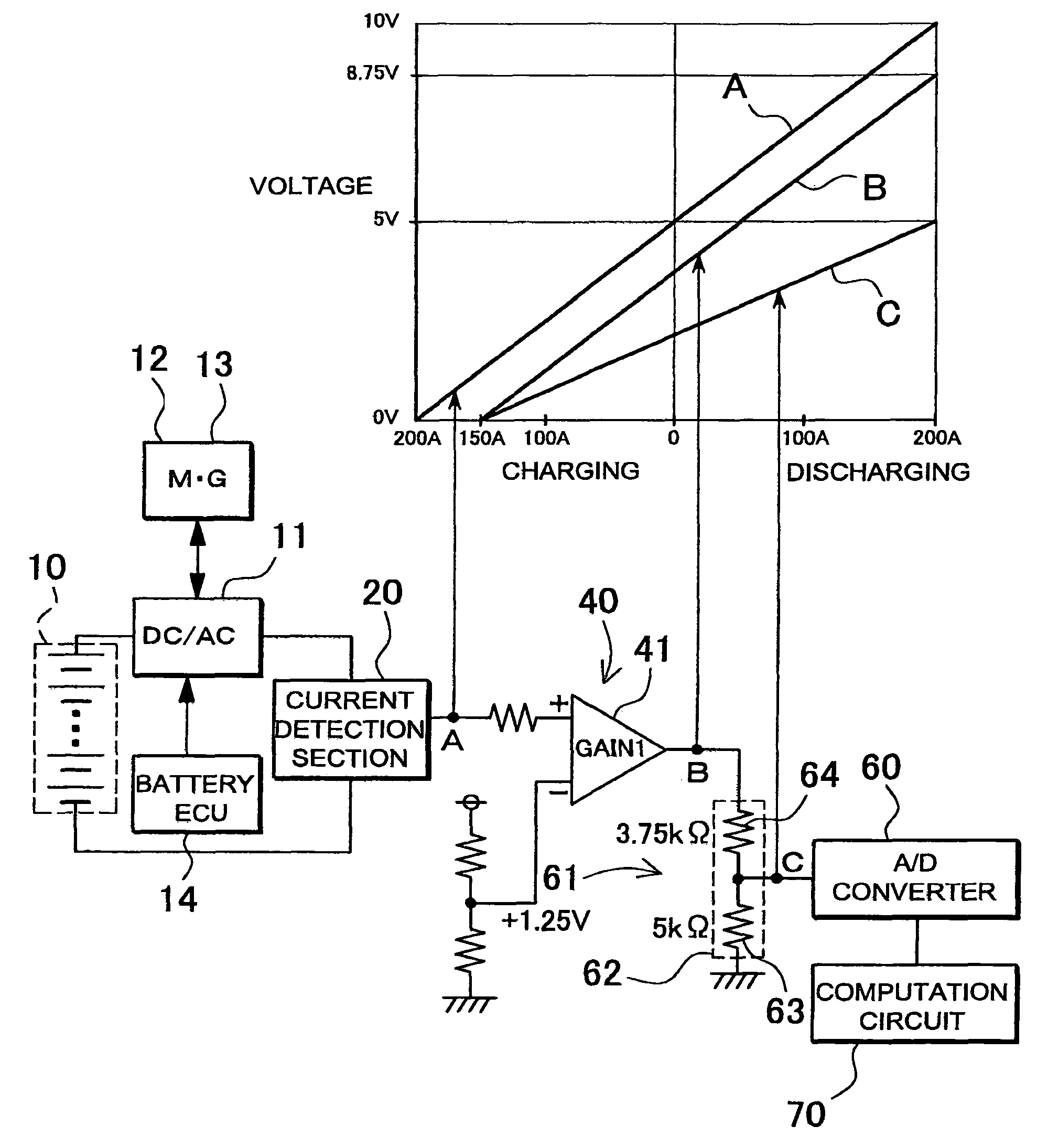
[0027]The current detection apparatus for a car power source shown in FIGS. 4-7 is provided with a current detection section 20, 30 to detect the charging current and discharging current of a driving battery 10 installed in a car, a level-shift circuit 40, 50 connected to the output-side of the current detection section 20, 30 to shift the output of the current detection section 20, 30, and an A / D converter 60 connected to the output-side of the level-shift circuit 40, 50.

[0028]The driving battery 10 of the car power source is connected to a motor 12 and generator 13 through a DC / AC inverter 11. The motor 12 discharges the battery 10, and the generator 13 charges the battery 10. Battery 10 discharging current and charging current are controlled by the battery ECU 14. The battery ECU 14 controls motor 12 discharging current based on vehicle driving conditions and battery 10 remaining capacity. Specifically, the battery ECU 14 controls motor 12 output to control power that drives the ...


PUM


Abstract

A current detection apparatus includes a current detection section that detects charging current and discharging current of the car driving battery, a level-shift circuit connected to the output-side of the current detection section that shifts the output of the current detection section, and an A / D converter connected to the output-side of the level-shift circuit. The level-shift circuit shifts the current detection section output signal to unbalance the maximum discharging current and maximum charging current that can be detected.

Description

BACKGROUND OF THE INVENTION[0001]1. Field of the Invention[0002]The present invention relates to a current detection apparatus to detect driving battery charging current and discharging current in a car power source apparatus.[0003]2. Description of the Related Art[0004]In a car power source apparatus, it is important to accurately compute remaining capacity of the driving battery. If error develops in detecting remaining battery capacity, that error accumulates as driving time increases. Cumulative error, which is the difference in remaining capacity between actual remaining battery capacity and computed remaining battery capacity, can become a cause of battery over-charging and battery over-discharging. Battery electrical characteristics degrade markedly with over-charging and over-discharging leading to shorter battery lifetime. Since a car driving battery is extremely expensive, it is important to enable its use for as long a period as possible. Further, in limiting the range of...

Claims


Application Information

Patent Timeline
Patent Type & Authority Patents(United States)
IPC IPC(8): H02J7/00
CPCG01R31/3648B60R16/03G01R19/25G01R31/007G01R31/3613G01R31/3832
Inventor MATSUMOTO, AKIRAYUGOU, MASAKI
Owner SANYO ELECTRIC CO LTD
Why Eureka
Try Eureka