Al technical title is built by PatSnap Al team. It summarizes the technical point description of the patent document.
a tactile responsiveness and interface technology, applied in the field of user interface devices, can solve the problems of limiting the flexibility of visual source material composition systems, significantly increasing the complexity, cost and hardware requirements of flexible systems, disadvantageous wear of actuators, and deterioration of tactile responsiveness, so as to facilitate flexible programming of various torque profiles
Inactive Publication Date: 2010-10-12
IMMERSION CORPORATION
View PDF429 Cites 13 Cited by
Summary
Abstract
Description
Claims
Application Information
AI Technical Summary
This helps you quickly interpret patents by identifying the three key elements:
Problems solved by technology
Method used
Benefits of technology
[0012]The present invention provides an actuator having electronically controllable tactile responsiveness which is flexibly programmable to facilitate provision in a single actuator of torque-position characteristics, such as a selectable number of detents per actuation through its full operative path. In an illustrative case of a rotary actuator the present invention facilitates provision in a single actuator, of torque versus angular position characteristics, such as a selectable number of detents per revolution.
[0014]In further accord with the invention, the controller is a microprocessor which receives position information, from the encoder, through a counter as a position count. Torque-position relation information is stored in microprocessor accessible firmware as a table containing a series of particular torque values corresponding to a series of particular position values. The torque values, output as digital signals and converted by a digital to analog converter, can be modified in accordance with a plurality of stored torque versus position tables to facilitate flexible programming of various torque profiles.
[0018]Features of the invention include the capability to effect tactile screen boundaries, and “walls” and “troughs” which correspond to button bar functions or icon placement on a drag-down menu, by increasing and decreasing resistance to further manipulation of the interface device by the user, or by aiding motion of the device. “Bumps” and other textures can be implemented on the screen display and tactilely perceived as the cursor is moved. Cell boundaries can be defined by hard stops or “hills” which a cursor will roll off to limit access to screen areas or otherwise provide an indication of cursor position without requiring the user to look at the screen. Different tactile response profiles can be stored to correspond to different screen displays and user applications. Physically impaired people can interface to computer applications without the need for sight or fine motor skills.
Problems solved by technology
Differing frame rate standards relating to visual source material and the nature of mechanical detents in actuators, presents the problem that multiple actuators are required to facilitate correlation between actuator tactile responsiveness and the various visual source material standards.
The plurality of actuators required limits the flexibility of visual source material composition systems and significantly increases the complexity, cost and hardware requirements of a flexible system.
In addition to the lack of flexibility of use of fixed mechanical detent actuators, such actuators disadvantageously become worn and suffer tactile responsiveness degradation over time.
Other mechanically / spring loaded linear or rotary actuators suffer similar deficiencies.
Disadvantageously, the magnetic pad surface is a requirement in such an embodiment, and the friction forces between the pad and the mouse may be affected in ways that may not be predictable and might be detrimental to the tactile responsiveness.
However, while the electromagnetic brake provides a stopping mechanism, it cannot provide a continuous torque to the tracking element, i.e. no torque is applied when the tracking element is stopped.
Such a mechanism cannot be used to change tactile responsiveness, e.g. to decrease resistance, as a function of characteristics of a particular screen display.
The resistance provided is only opposed to motion and cannot aid motion by actively driving the ball to facilitate ease of motion in certain display areas or to keep the cursor off of the boundary of a restricted display area.
Method used
Image
Click on the blue label to locate the original text in one second.
Reading with bidirectional positioning of images and text.
Examples
Embodiment Construction
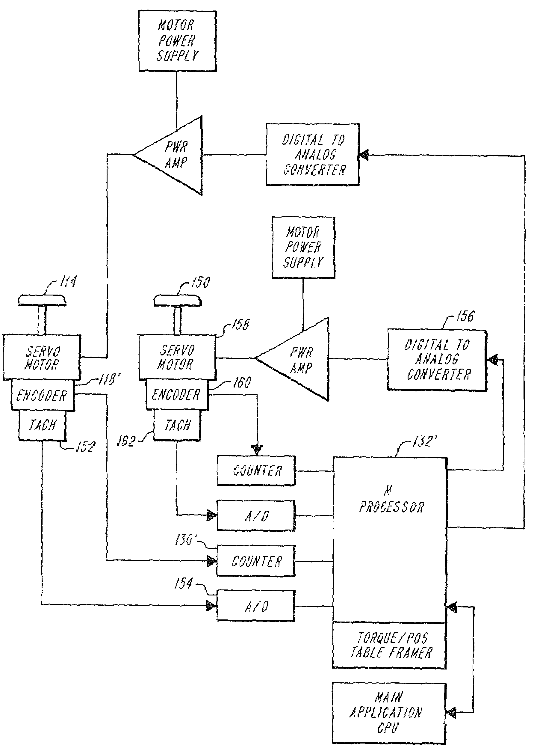
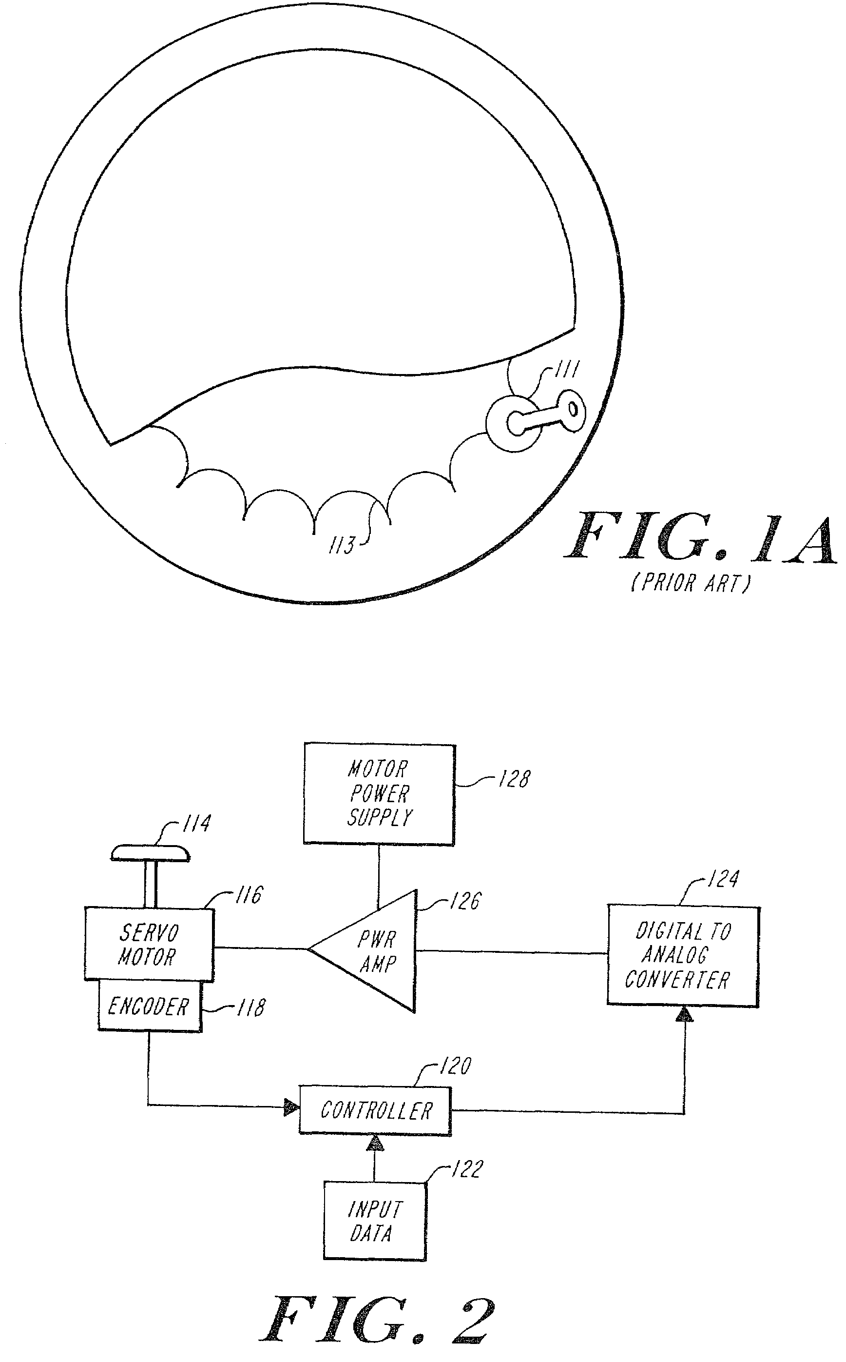
[0037]Referring now to FIG. 2, an actuator, such as a rotary actuator having a control knob 114 is attached via a shaft to a servo motor 116. In this illustrative embodiment wherein the actuator is for use in a film / video editing context, the servo motor is a PMI 12FVS motor. In the present application, as discussed in greater detail hereinafter, the servo motor is not used as a motor per se, but rather as a torque controller. The motor never runs at a significant amount of its rated revolutions per minute, but operates normally in this application in a stalled or semi-stalled state. The preferred motor 116 has an installed encoder 118. The encoder 118 is a PMI M23, 300 segment modular encoder having an index and providing 300 cycles per revolution, which results in 1200 waveform edges from index to index. Note that in this illustrative embodiment it is important that the encoder be selected to provide a number of edges which is divisible by factors of two, three, five and eight. Th...
PUM
Property
Measurement
Unit
time
aaaaa
aaaaa
torque
aaaaa
aaaaa
time
aaaaa
aaaaa
Abstract
A method and apparatus implementing a user interface device, such as a mouse or trackball, having electronically controllable tactile responsiveness which is flexibly programmable. A user interface device effects positioning of a cursor within a limited area, such as on a display screen, with limits imposed by controllable tactile responsiveness. Programmable force-position characteristics relate the tactile responsiveness of the interface device to the position of the cursor within the limited area or on the display screen. In a described embodiment, the interface device includes at least two sets of wheels that move as the interface device is actuated. The at least two sets of wheels are aligned on mutually orthogonal axes. A servo motor is attached to each of the at least two sets of wheels. A position encoder is associated with each servo motor and outputs position information to a controller that has access to force-position relation information that is a function of a screen display on which the cursor is manipulated. The controller outputs a digital signal, in accordance with the force-display position relation information. The digital signal is converted to an analog current signal applied to the servo motor(s) to generate force in the servo motor. The force, presenting a tactile response to a human interacting with the user interface device, is perceived as a resistance, tactile pressure or lack thereof, or as a positive, assisted motion which is indicative of position on a screen display.
Description
[0001]This is a continuation of of prior U.S. application Ser. No. 09 / 253,392, filed on Feb. 19, 1999, now U.S. Pat. No. 6,876,891 which is a continuation of U.S. patent application Ser. No. 08 / 585,198, filed Jan. 11, 1996, issued as U.S. Pat. No. 5,889,670, incorporated herein by reference, which is a continuation-in-part of U.S. patent application Ser. No. 08 / 434,176, filed May 3, 1995, issued as U.S. Pat. No. 5,559,412, which is a continuation of U.S. patent application Ser. No. 08 / 076,344, filed Jun. 11, 1993, issued as U.S. Pat. No. 5,414,337, which is a continuation-in-part of U.S. patent application Ser. No. 07 / 783,635, filed Oct. 24, 1991, issued as U.S. Pat. No. 5,220,260.FIELD OF THE INVENTION[0002]The present invention relates to user interface devices and in particular to devices providing tactile responsiveness and having programmable force-position profiles defining tactile responsiveness in manipulating a cursor on a screen display.BACKGROUND OF THE INVENTION[0003]In ...
Claims
Application Information
Patent Timeline
Application Date:The date an application was filed.
Publication Date:The date a patent or application was officially published.
First Publication Date:The earliest publication date of a patent with the same application number.
Issue Date:Publication date of the patent grant document.
PCT Entry Date:The Entry date of PCT National Phase.
Estimated Expiry Date:The statutory expiry date of a patent right according to the Patent Law, and it is the longest term of protection that the patent right can achieve without the termination of the patent right due to other reasons(Term extension factor has been taken into account ).
Invalid Date:Actual expiry date is based on effective date or publication date of legal transaction data of invalid patent.