

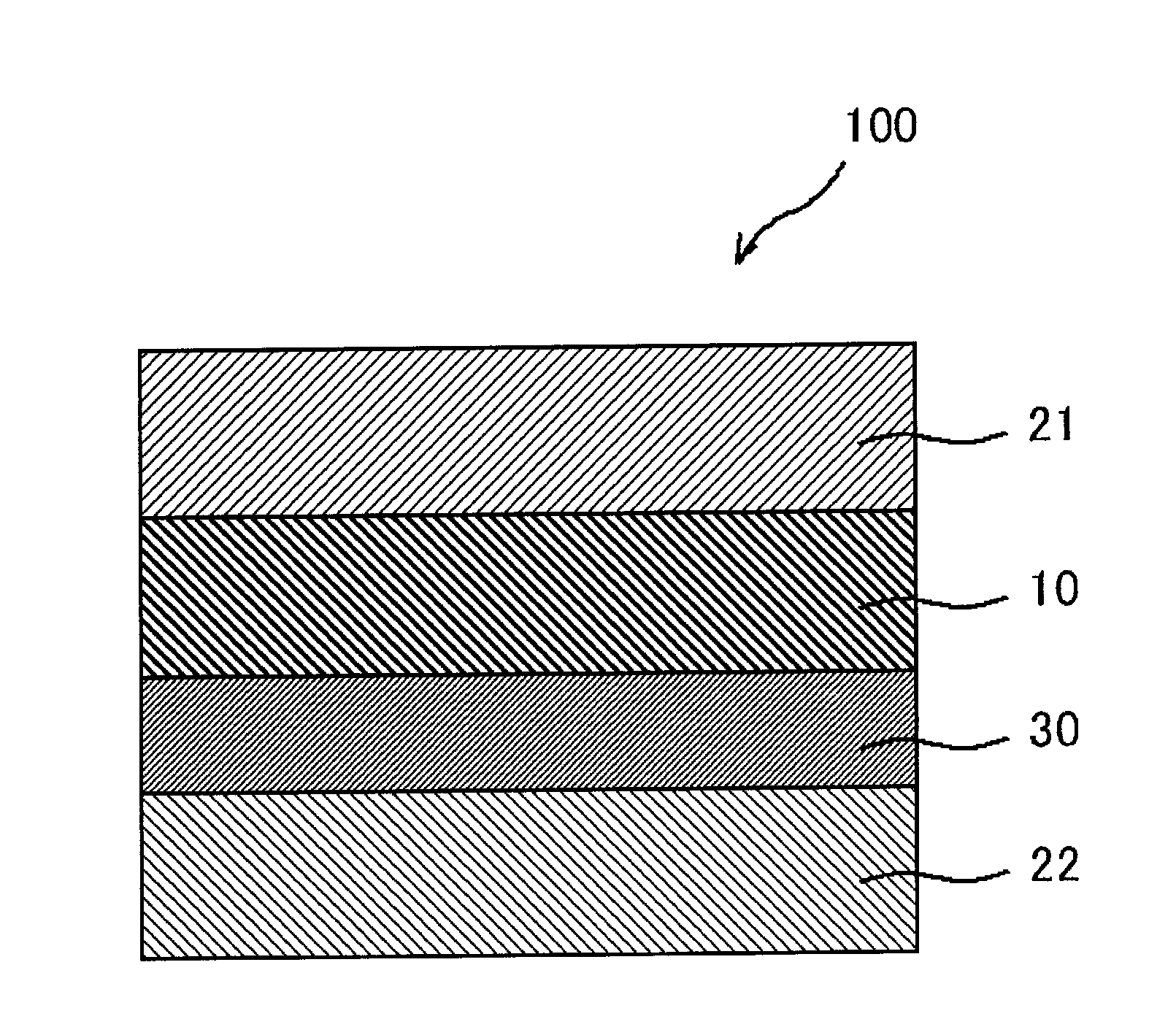
Liquid crystal panel and liquid crystal display apparatus
a liquid crystal display and liquid crystal technology, applied in the field of liquid crystal panels, can solve the problems of low contrast ratio in front and oblique directions, and achieve the effect of excellent display properties and high contras
- Summary
- Abstract
- Description
- Claims
- Application Information
AI Technical Summary
Benefits of technology
Problems solved by technology
Method used
Image

Examples
reference example 1
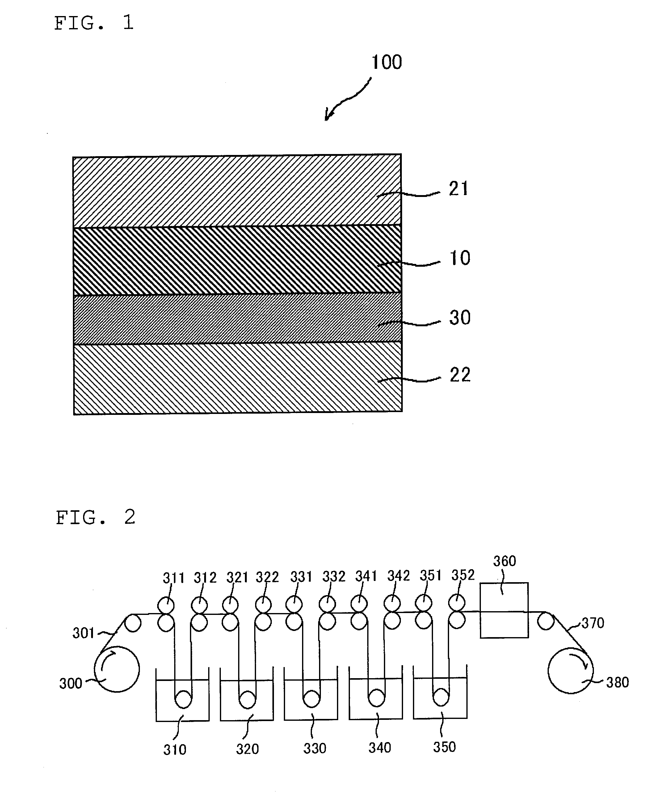
[0211]A polymer film (“VF-PS#7500” (trade name) manufacture by Kuraray Co., Ltd.) with a thickness of 75 μm containing a polyvinyl alcohol-based resin as a main component was soaked in 5 baths under the following conditions [1] to [5] while the tension was being applied to the film in a film longitudinal direction, and stretched so that the final stretching ratio became 6.2 times with respect to the film original length. The stretched film was dried in an air-circulating drying oven at 40° C. for one minute, whereby a polarizer A was produced. A polymer film (“TD80UF” (trade name); Re[590]=0 nm, Rth[590]=60 nm, manufactured by Fujifilm Corporation) with a thickness of 80 μm containing a cellulose-based resin was attached to both sides of the polarizer A via a water-soluble adhesive (GOHSEFIMER Z-200 (trade name) manufactured by Nippon Synthetic Chemical Industry Co., Ltd) containing a polyvinyl alcohol-based resin as a main component, whereby a polarizing plate A was produced. The p...
reference example 2
[0218]A polarizing plate B was produced by the same conditions and method as those in Reference Example 1, except that the adding amount of iodine in Condition [2] was 0.031 parts by weight with respect to 100 parts by weight of water. The properties of the polarizing plate B are shown in the following Table 1.
reference example 3
[0219]A polarizing plate C was produced by the same conditions and method as those in Reference Example 1, except that the adding amount of iodine in Condition [2] was 0.027 parts by weight with respect to 100 parts by weight of water. The properties of the polarizing plate C are shown in the following Table 1.
[0220]
TABLE 1ReferenceReferenceReferenceExample 1Example 2Example 3PolarizerABCThickness (μm)303030Light41.542.443.5transmittance(%)Degree of99.9999.9999.99polarization(%)Iodine content2.952.772.09(% by weight)Potassium content0.620.610.58(% by weight)Boric acid content222(% by weight)
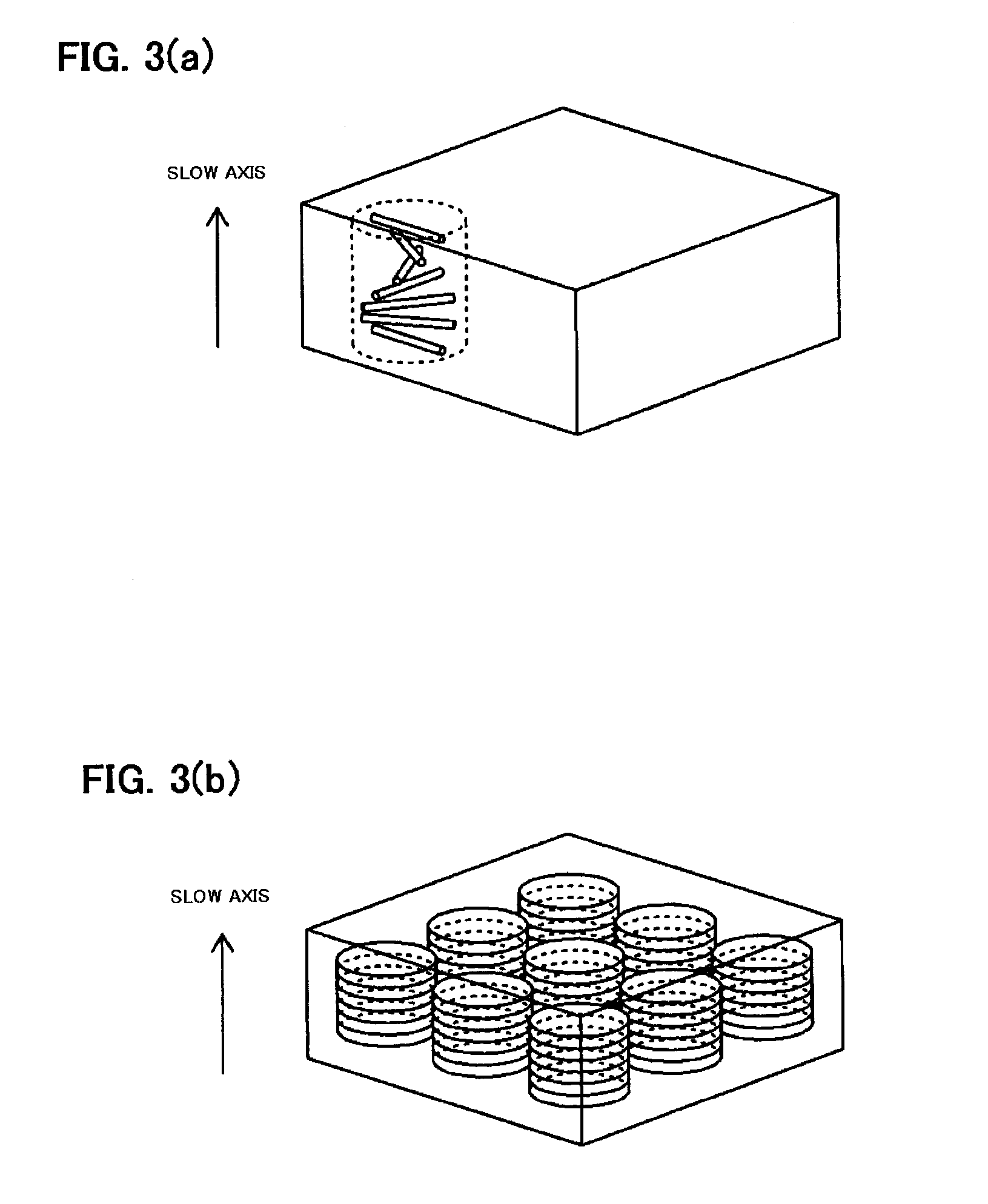
Production of a Retardation Layer
PUM
| Property | Measurement | Unit |
|---|---|---|
| light transmittance | aaaaa | aaaaa |
| wavelength | aaaaa | aaaaa |
| wavelength | aaaaa | aaaaa |
Abstract
Description
Claims
Application Information