Gyro sensor module and angular velocity detection method

a technology of angular velocity and sensor module, which is applied in the direction of acceleration measurement using interia force, turn-sensitive devices, instruments, etc., can solve the problems of reducing detection accuracy, reducing signal-to-noise ratio, and reducing detection sensitivity, so as to improve detection accuracy, reduce the angle formed by the detection axes and the detected axis, and increase detection accuracy

Inactive Publication Date: 2010-10-19
SEIKO EPSON CORP
View PDF7 Cites 33 Cited by
  • Summary
  • Abstract
  • Description
  • Claims
  • Application Information

AI Technical Summary

Benefits of technology

[0009]An advantage of the invention is to provide a gyro sensor module and an angular velocity detection method that each increases the detection accuracy regardless of to what extent the mounting angle of the detection axis changes.
[0010]According to a first aspect of the invention, a gyro sensor module built into a navigation system mounted into a mobile unit includes: a first gyro sensor detecting and outputting a first angular velocity ω1 around a first detection axis; a sign determination circuit for determining a sign of the first angular velocity ω1; a second gyro sensor detecting and outputting a second angular velocity ω2 around a second detection axis intersecting the first detection axis at an acute angle θ12; a sensor output correction circuit for correcting outputs of the first and second gyro sensors; and a computation circuit for computing ω′ by equations ω′=√(ω1′2+SA2) and SA=(ω2′−ω1′ cos θ12) / sin θ12 using a first angular velocity ω1′ and a second angular velocity ω2′ obtained by a correction performed by the sensor output correction circuit, and outputting an angular velocity ω obtained by multiplying the ω′ by the sign of the first angular velocity ω1 obtained by the sign determination circuit. The sensor output correction circuit includes: a first offset adjustment circuit for outputting a value ω1″ obtained by subtracting from the ω1 a correction value B1 corresponding to an output value of the first gyro sensor at a time when the mobile unit in which the gyro sensor module is disposed is stopping; and a second offset adjustment circuit for outputting a value ω2″ obtained by subtracting from the ω2 a correction value B2 corresponding to an output value of the second gyro sensor at a time when the mobile unit in which the gyro sensor module is disposed is stopping. The angular velocity ω is an angular velocity around an axis located in a plane including the first and second detection axes and in a range between the first and second detection axes.
[0011]According to the first aspect of the invention, the first and second angular velocities ω1 and ω2 are converted into the first and second angular velocities ω1″ and ω2″ by the first and second offset adjustment circuits included in the sensor output correction circuit, by subtracting the output value B1 of the first gyro sensor and the output value B2 of the second gyro sensor at a time when the mobile unit is stopping from the first and second angular velocities ω1 and ω2. Thus, the more accurate first and second angular velocities ω1″ and ω2″ at a time when the vehicle 102 is moving are obtained.
[0012]Also, the angular velocity ω around the detected axis perpendicular to the horizontal ground surface is detected by synthesizing the angular velocities measured on the two detection axes regardless of to what extent the mounting angle of each detection axis changes or to what extent the angle that each detection axis forms with the horizontal ground surface changes.
[0013]The angle formed by the first and second detection axes is an acute angle, and the angular velocity ω is detected in the acute angle. Therefore, the angle formed by the detection axes and the detected axis is reduced. This allows a gyro sensor module having a good detection accuracy to be obtained.
[0014]The acute angle is preferably 20° to 60°, more preferably 30° to 50°. Variations in inclination of a vehicle or the like are on the order of 40° at maximum even if upward slopes and downward slopes of a road are considered. If the acute angle is less than 20°, the detected axis easily gets out of the range between the first and second detection axes, thereby making it difficult to obtain a high detection accuracy. Also, variations in inclination of a vehicle or the like on an ordinary road are rarely 60° or more.

Problems solved by technology

On the other hand, an orthogonality between the detection axis and the detected axis reduces the detection sensitivity, thereby reducing the signal-to-noise ratio to reduce the detection accuracy.
Therefore, the movable range of the mounting angle of the detection axis is limited.
This makes it difficult to increase the detection accuracy.
However, the inventors have found that a detection error occurs due to the first and second gyro sensors both having undergone no offset process.
If the acute angle is less than 20°, the detected axis easily gets out of the range between the first and second detection axes, thereby making it difficult to obtain a high detection accuracy.

Method used


Image

  • Gyro sensor module and angular velocity detection method
  • Gyro sensor module and angular velocity detection method
  • Gyro sensor module and angular velocity detection method

Examples


first embodiment

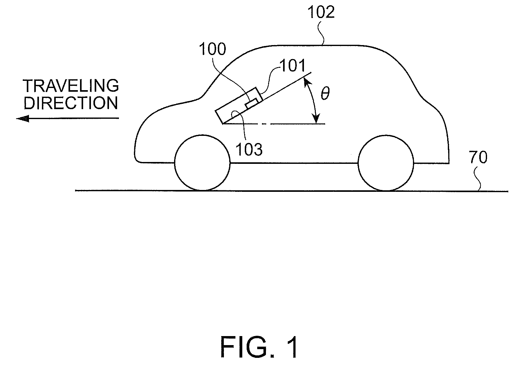
[0037]FIG. 1 is a schematic drawing showing a state in which a navigation system 101 including a gyro sensor module 100 according to a first embodiment of the invention is mounted in a vehicle 102 that is a mobile unit. In FIG. 1, the navigation system 101 is mounted in the front part of the vehicle 102. The vehicle 102 moves toward the left side of the paper surface. The navigation system 101 is mounted at an angle θ formed by a bottom thereof 103 and a horizontal ground surface 70. The gyro sensor module 100 is mounted on the bottom 103 of the navigation system 101.

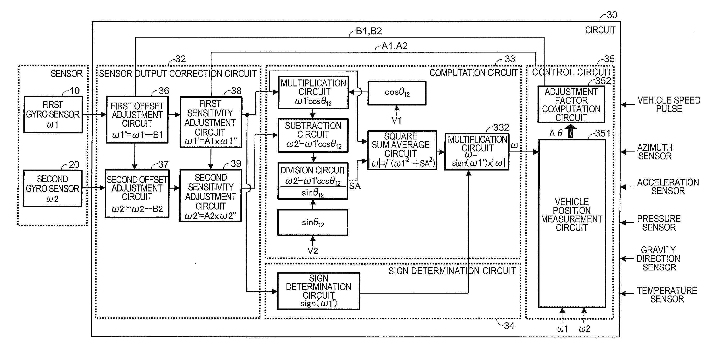
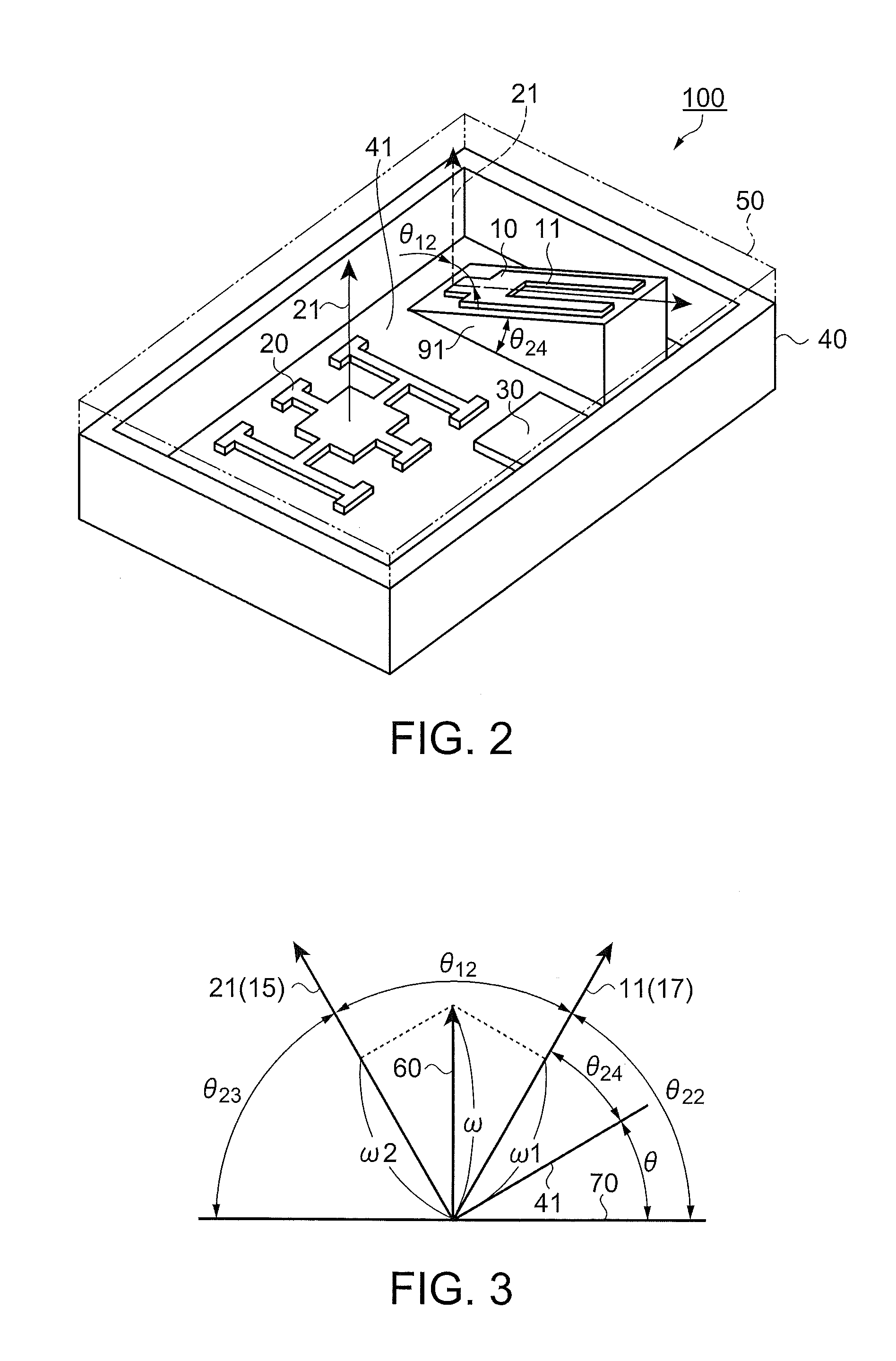
[0038]FIG. 2 is a schematic perspective view showing the gyro sensor module 100 according to this embodiment. In FIG. 2, the gyro sensor module 100 includes a first gyro sensor 10, a second gyro sensor 20, a circuit 30, a box-shaped package 40, and a lid 50. The first gyro sensor 10, the second gyro sensor 20, and the circuit 30 are disposed on a rectangular bottom 41 of the package 40.

[0039]The first gyro sensor 10 is ...

second embodiment

[0074]FIG. 5 is a schematic perspective view showing a gyro sensor module 200 according to a second embodiment of the invention. The gyro sensor module 200 includes a first gyro sensor module 12, a second gyro sensor module 22, and a base 80 having a rectangular mounting surface 81.

[0075]In the first gyro sensor 12, a tuning fork-shaped vibrator is mounted in a package having a rectangular mounting surface 13. A first detection axis 11 of the first gyro sensor 12 is mounted on the mounting surface 13 so as to be a longitudinal edge of the mounting surface 13. The first gyro sensor 12 is disposed on a slope of a base 90 disposed on the mounting surface 81. Therefore, the first detection axis is inclined toward the mounting surface 81.

[0076]In the second gyro sensor 22, a double T-shaped vibrator that is a combination of two T-shaped vibrators is mounted in a package having a rectangular mounting surface 23. The double T-shaped vibrator is mounted so that a second detection axis 21 th...

third embodiment

[0080]FIG. 6 is a schematic perspective view showing a gyro sensor module 300 according to a third embodiment of the invention. In FIG. 6, the gyro sensor module 300 includes the first gyro sensor 10, a second gyro sensor 14, the circuit 30, the box-shaped package 40, and the lid 50. The first gyro sensor 10, the second gyro sensor 14, and the circuit 30 are disposed on a rectangular bottom 41 of the package 40.

[0081]The first and second gyro sensors 10 and 14 are tuning fork-shaped gyro sensors and are disposed so that the angle θ12 formed by a first detection axis 17 of the first gyro sensor 10 and a second detection axis 15 of the second gyro sensor 14 is an acute angle.

[0082]The gyro sensor module 300 is mounted into a vehicle or the like so that a plane including the first detection axis 17 and the second detection axis 15 is orthogonal to the horizontal ground surface 70 as shown in FIG. 3.

[0083]Specifically, the gyro sensor module 300 is mounted so that the bottom 41 is ortho...


PUM


Abstract

A mobile navigation system gyro module comprises: first and second gyro sensors outputting angular velocities ω1, ω2 around first and second axes intersecting at an acute angle θ12; a sign determination circuit determining a sign of ω1; a correction circuit correcting the first and second gyro sensor outputs; and a computation circuit computing ω′=√(ω1′2+SA2) and SA=(ω2′−ω1′ cos θ12) / sin θ12 using angular velocities ω1′, ω2′ from the correction circuit, and outputting angular velocity ω by multiplying ω′ by the sign of ω1, wherein the correction circuit includes: first and second offset adjustment circuits outputting ω1″ and ω2″ by respectively subtracting from ω1 and ω2, corrections B1 and B2 corresponding to the first and second gyro sensor outputs when the mobile unit stops; and the angular velocity ω is around an axis coplanar with and between the first and second axes.

Description

BACKGROUND[0001]1. Technical Field[0002]The present invention relates to a gyro sensor module for detecting an angular velocity to know an azimuth and an angular velocity detection method.[0003]2. Related Art[0004]A gyro sensor is used in a navigation system mounted in a vehicle or the like. The angular velocity to be detected by the gyro sensor when the vehicle makes a turn is used to know the azimuth of the vehicle. In order to detect the angular velocity accurately, the angular velocity detection axis and the detected axis of the gyro sensor must be matched. The detected axis to be used to know the azimuth is an axis perpendicular to the horizontal ground surface. A match between the detection axis and the detected axis increases the detection sensitivity, thereby increasing the signal-to-noise ratio to increase the detection accuracy. On the other hand, an orthogonality between the detection axis and the detected axis reduces the detection sensitivity, thereby reducing the signa...

Claims


Application Information

Patent Timeline
Patent Type & Authority Patents(United States)
IPC IPC(8): G01C19/00G01P21/00G01P3/04
CPCG01C19/56G01C21/12G01C25/005
Inventor SATO, KENJI
Owner SEIKO EPSON CORP
Why Eureka
Try Eureka