Stepped light collection and concentration system, components thereof, and methods

a light collection and concentration system technology, applied in the field of optical light guides, can solve problems such as non-ideal light guides

Active Publication Date: 2010-10-19
UNIVERSITY OF ROCHESTER +1
View PDF17 Cites 38 Cited by
  • Summary
  • Abstract
  • Description
  • Claims
  • Application Information

AI Technical Summary

Benefits of technology

[0011]An embodiment of the invention is a component light guide. The light guide includes a light guide layer having a top surface and a bottom surface, at least one of which is a substantially planar surface, and a transversely oriented side-end surface that forms a primary output aperture (exit) for light traveling in a forward propagation direction out of the end surface of the light guide (for, e.g., CPV applications) and, which forms a primary input aperture (entrance) for light traveling in a rearward propagation direction into the end surface of the light guide (for, e.g., illuminator applications), characterized by an index of refraction, n1; and a first plurality of light injection elements disposed in at least one of the top and bottom surfaces and extending inwardly therefrom at an angle to the ...

Problems solved by technology

By concentrating solar energy with optics, less photovoltaic (PV) material is used, reducing cost, since PVs are expensive and energy-intensive to produce compared with optical components.
The presen...

Method used


Image

  • Stepped light collection and concentration system, components thereof, and methods
  • Stepped light collection and concentration system, components thereof, and methods
  • Stepped light collection and concentration system, components thereof, and methods

Examples


Embodiment Construction

[0029]Reference will now be made in detail to the present exemplary embodiments of the invention, examples of which are illustrated in the accompanying drawings. Wherever possible, the same reference numbers will be used throughout the drawings to refer to the same or like parts.

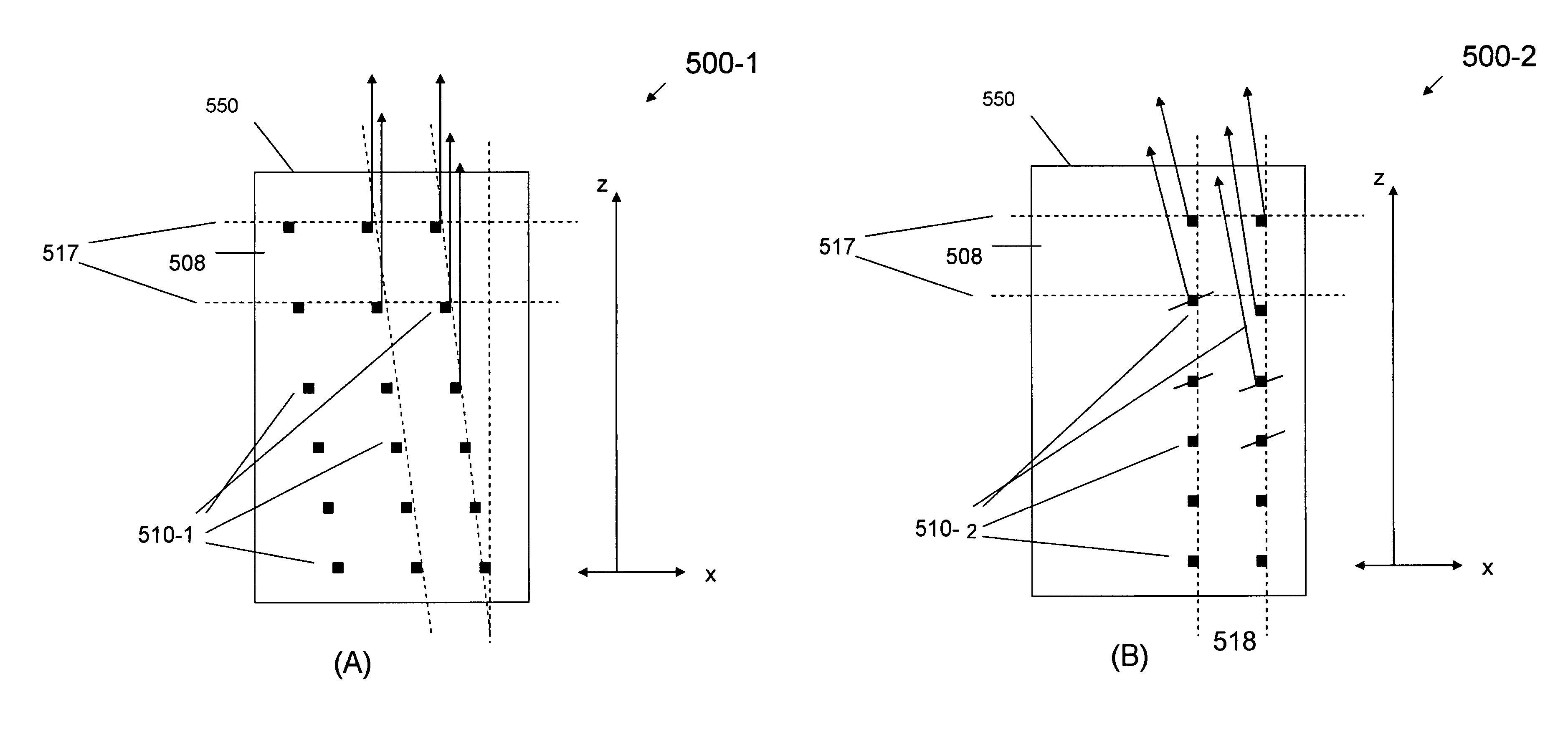
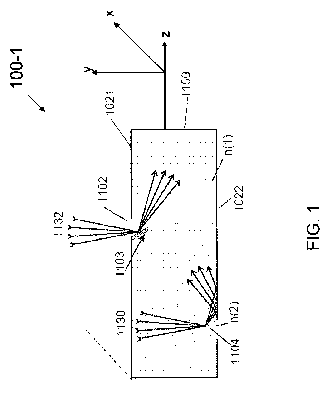
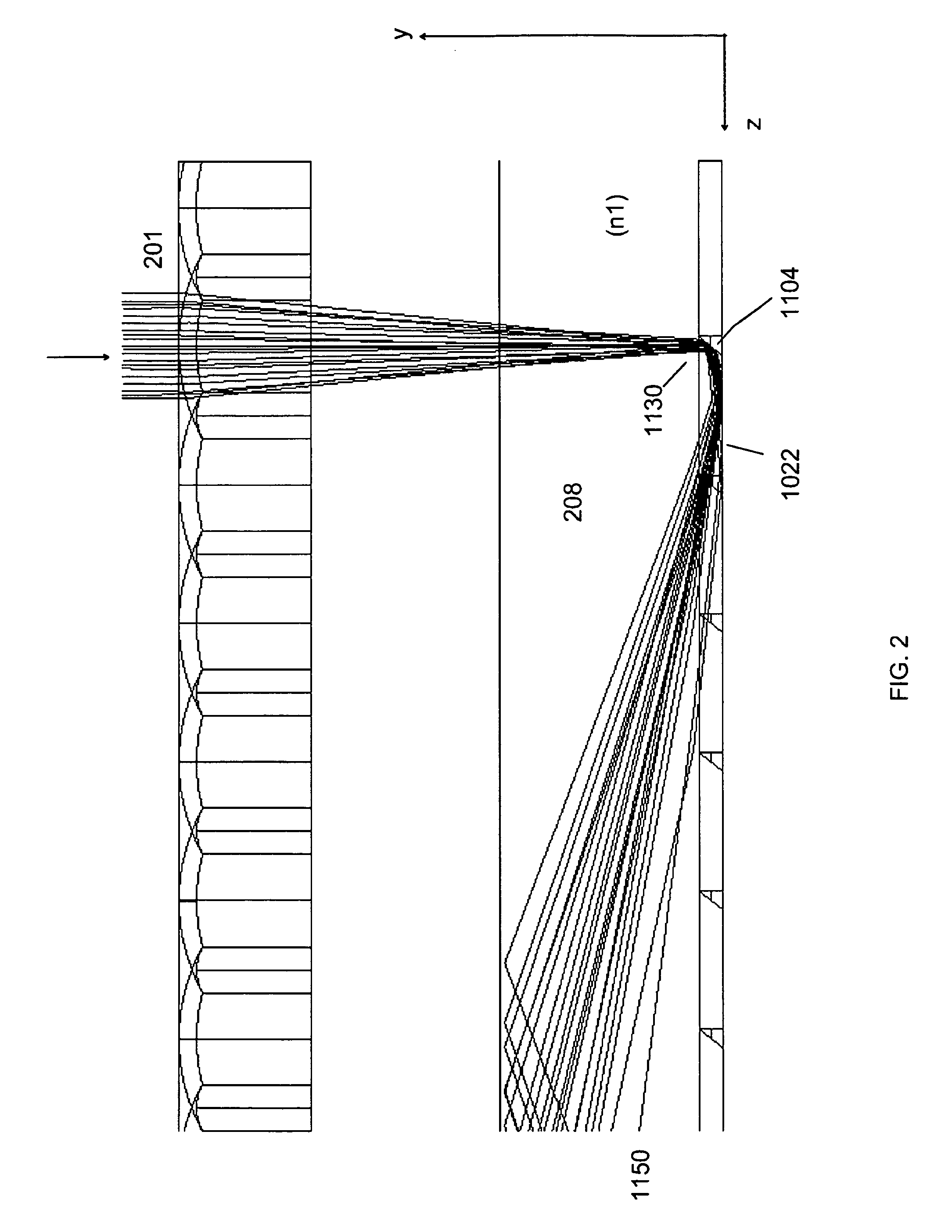
[0030]Concurrently filed application Ser. No. 12 / 490,417 entitled Light Collection and Concentration System, Components Thereof and Methods, discloses, among other things, a dimpled light guide component as well as a light collection and concentration system incorporating a dimpled light guide component. As discussed therein, various structural light bypass elements and light injection elements were incorporated into the component light guide to optimize light propagation within the guide that would otherwise be reduced due to light loss from the light injection elements themselves.

[0031]According to an embodiment of the invention described herein, a different structural layout of the component light guide i...


PUM


Abstract

A light guide includes a light guide layer having a transversely oriented side-end surface that forms a primary output aperture (exit) for light traveling in a forward propagation direction out of the end surface of the light guide (for, e.g., CPV applications) and, which forms a primary input aperture (entrance) for light traveling in a rearward propagation direction into the end surface of the light guide (for, e.g., illuminator applications), and a first plurality of light injection elements stepped (staggered) in a forward light propagation direction in a first plane along lines parallel to the side-end surface or clocked (tilted) about a y-axis in a z-axis-light propagation direction in a respective first plane, wherein the light injection elements are disposed along parallel lines normal to the side-end surface. The light guide component may further comprise at least a second plurality of light injection elements stepped in at least second plane. A light guide system includes a component light guide, a lenslet array disposed adjacent a top surface of the light guide, and a light-transmitting, TIR medium layer disposed immediately adjacent at least one of the top and bottom surfaces of the light guide.

Description

CROSS-REFERENCE TO RELATED APPLICATIONS[0001]This application is a Divisional application of U.S. Ser. No. 12 / 490,417 entitled Dimpled Light Collection and Concentration System, Components Thereof and Methods, filed concurrently with the instant application, the disclosure of which is incorporated by reference herein in its entirety.JOINT RESEARCH AGREEMENT[0002]This application is derived from a pre-existing Joint Research Agreement between the assignee of the instant application, the University of Rochester, and Abengoa Solar New Technologies, S.A.BACKGROUND OF THE INVENTION[0003]1. Field of the Invention[0004]Embodiments of the invention relate generally to the field of optical light guides and, more particularly, to non-imaging, light guide concentrator and illuminator systems, methods, and applications. Even more particularly, embodiments of the invention relate to a light collection and concentration system used in a concentrated photo-voltaic (CPV) solar energy application, a...

Claims


Application Information

Patent Timeline
IPC IPC(8): G02B6/26H01L31/00
CPCF24J2/08F24J2/18G02B6/0036H01L31/0547G02B6/0053H01L31/0543G02B6/0048F24J2002/108F24J2002/1095Y02E10/40Y02E10/52F24S2023/878F24S23/79F24S2023/872F24S23/30
Inventor MOORE, DUNCAN T.SCHMIDT, GREG R.UNGER, BLAIR L.
Owner UNIVERSITY OF ROCHESTER
Why Eureka
Try Eureka