Block and connector system

a technology of connectors and blocks, applied in the direction of load-supporting elements, structural elements, building components, etc., can solve the problems of difficult to achieve a tight and stiff fit at the block joint, poor overall performance, and very rarely used systems in the practice of building walls, and achieve low cost and limit thermal conductivity

Active Publication Date: 2010-10-26
LEMIEUX GUY
View PDF13 Cites 8 Cited by
  • Summary
  • Abstract
  • Description
  • Claims
  • Application Information

AI Technical Summary

Benefits of technology

[0010]The present invention reduces the limitations, difficulties and disadvantages of the aforesaid designs by providing a block and connector system for erecting structures such as building walls, which can be assembled providing positive lock of the blocks and vertical and horizontal passages adapted to many uses. As the block is a simple construction it is easy to manufacture with low manufacturing costs, and is not likely to be damaged or otherwise adversely affected by handling and construction site conditions. The Applicant has found the surprising discovery that such a spool-like connecting element co-operating with simple cut-outs at the free ends of upright walls of adjacent blocks overcomes the problems associated with the aforesaid designs. As the connecting element may be formed of a compliant or resilient material, a stiff and tight assembly can be easily and accurately performed without requiring excessive block molding tolerances and handling care. It will be appreciated that the embodiments according to the present invention obviate the limitations and drawbacks of the prior art blocks and systems, namely by improving block resistance to damages and thermal conductivity, stiffness of the assembly and in-wall channeling, while reducing weight and production costs, thus enabling convenient use in a wide range of applications.
[0023]Advantageously, the invention provides a building block and connector system featuring stiff and tight interconnections between blocks in the axial and transversal directions of the courses, while providing vertical and horizontal passages within the erected structure. The block structure limits thermal conductivity, may be produced at low cost and is not likely to be affected by rough handling and adverse site conditions.

Problems solved by technology

However, such systems are very seldom used in practice for building walls, due to many limitations.
Therefore, many complex interlocking block structures incorporating connection members have been proposed.
Still, cement and aggregate based composite materials such as concrete being non compliant and brittle, it is difficult to achieve a stiff and tight fit at block joints even with slight dimensional mismatches or damages.
However, these are not found on the market given their generally poor overall performance and high manufacturing cost.
An important limitation of that system is that due to the complex structure of the blocks, block major walls must be thick to provide sufficient mechanical resistance to the brittle free ends and corners, so that for erecting a wall of a given thickness, more block material must be used and less passage space will be available.
Therefore, material costs are increased as well as thermal conductivity, and passages would be hard to access from the block surface and would allow very limited space for the passage of services.
Also, using non-compliant concrete elements to interconnect blocks limits stiffness and tightness of the assembly and is not well adapted for erecting structures without using stabilizing liquid cement.
Although it has a less complex and less damage sensitive structure than that of U.S. Pat. No. 4,075,808, this system for building blast bomb resistant walls does not provide locking or interconnecting means that would prevent axial displacement of the blocks if no added reinforcements were used as intended.
Still, block structure is complex, making molding delicate and costly, and making the brittle concrete block fragile and subject to damages during handling and installation.
In addition, narrow recesses may be partly filled with debris on a construction site, which might prevent proper fit of connecting elements.

Method used


Image

  • Block and connector system
  • Block and connector system
  • Block and connector system

Examples


Embodiment Construction

[0041]Although the present invention will be described with reference to embodiments mainly adapted for erecting structures such as building wall, persons skilled in the art will appreciate other applications of the present invention wherein variations in the shape of the block may be desirable. For example, external shapes and textures of the blocks may be adapted for use in erecting structures in landscaping, or size and material may be adapted for use as a toy building block system.

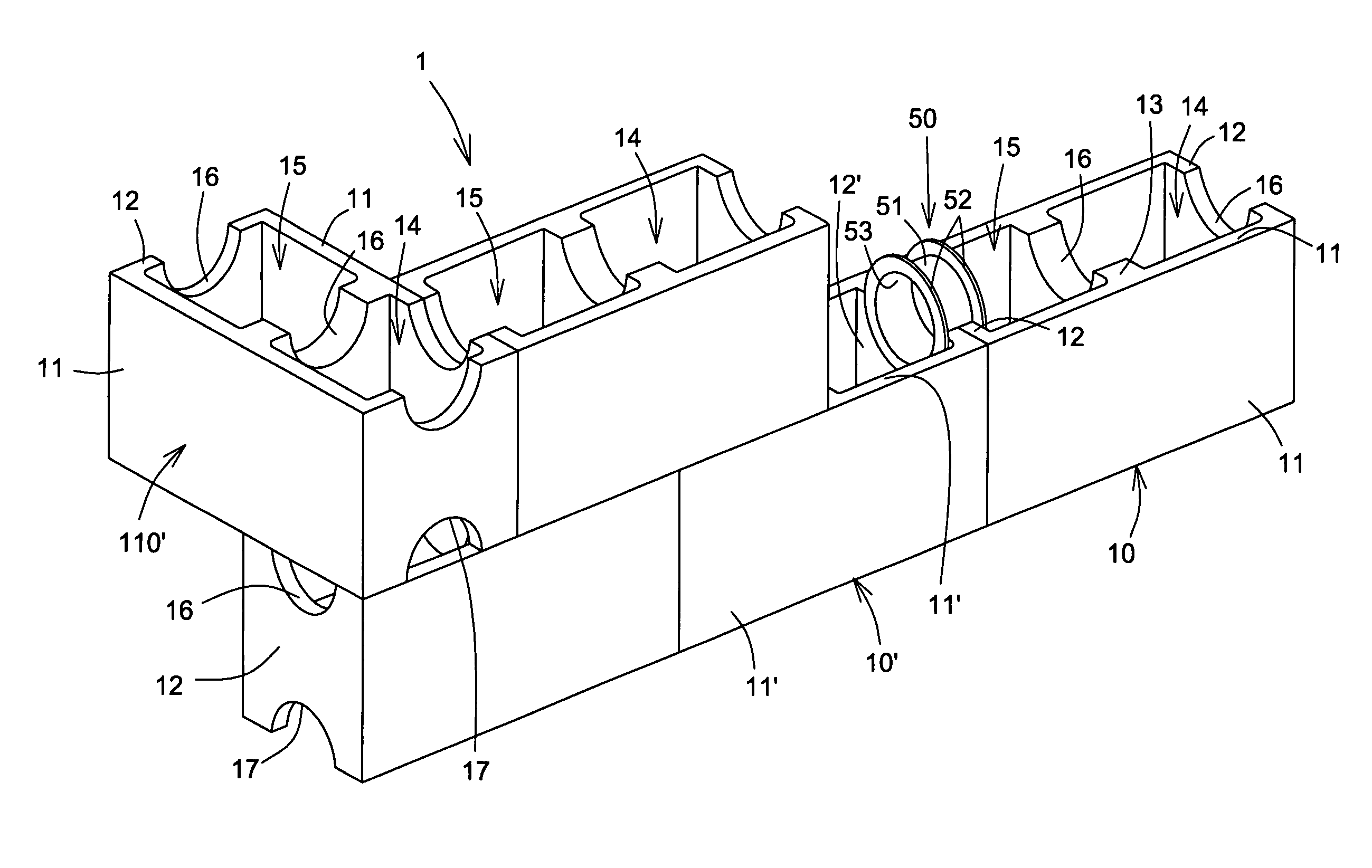
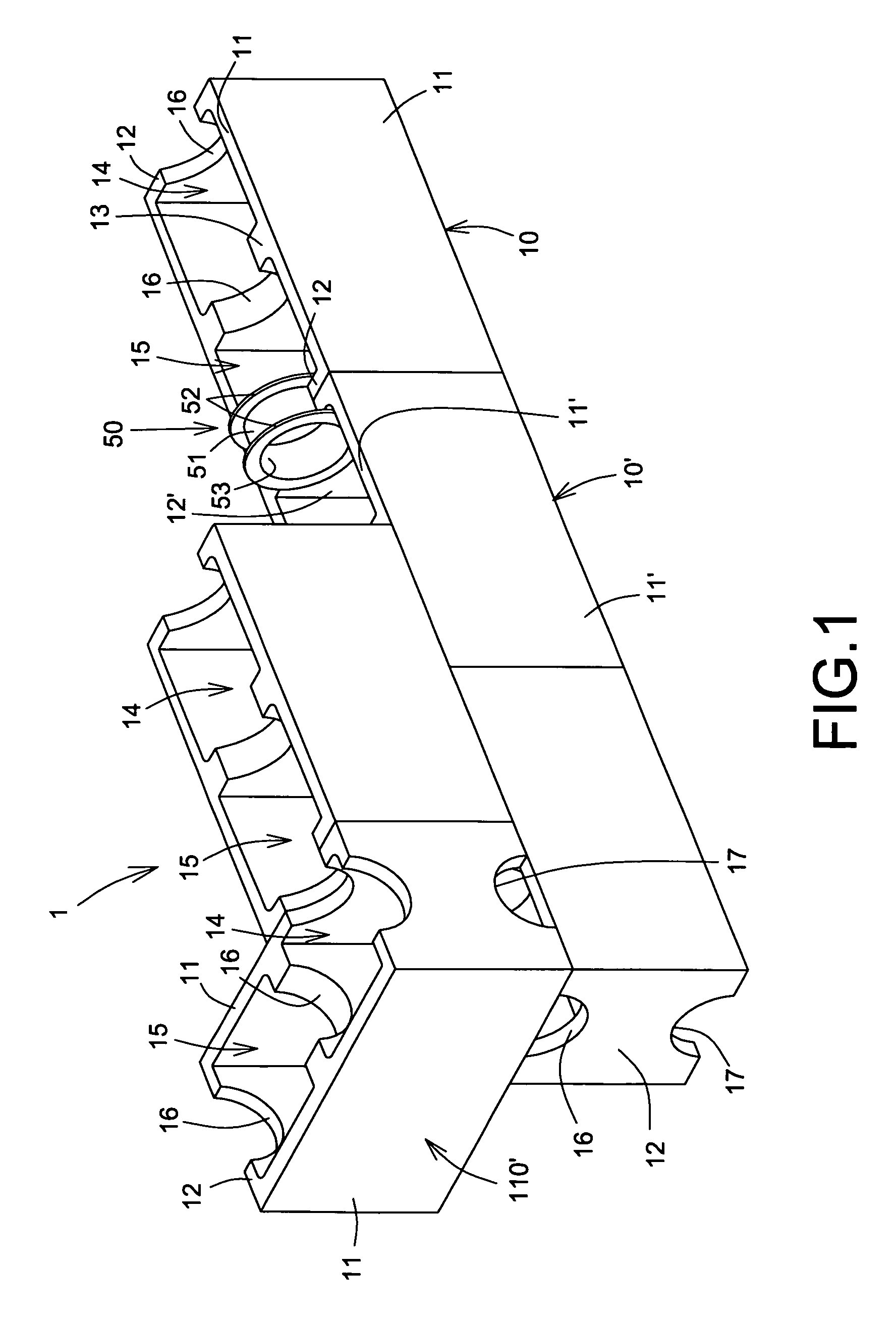
[0042]FIG. 1 shows a portion of a structure erected using a block and connector system 1 according to the present invention. The illustrated system 1 comprises hollow building blocks such as regular block 10 and special intersecting corner block 110′, and connectors such as spool-like connector 50.

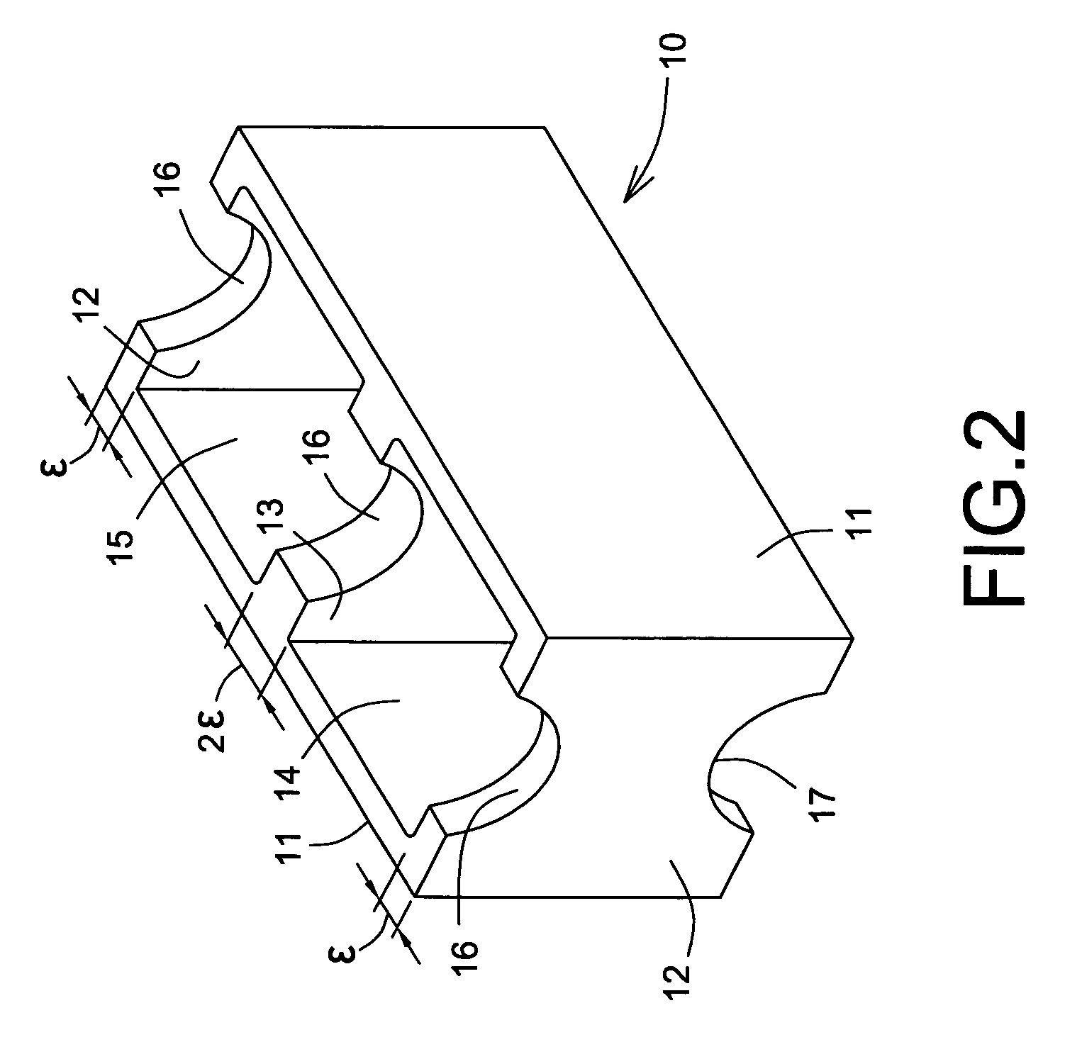
[0043]The regular block 10, best shown at FIG. 2, typically has a composite material composition using aggregates of fibers or like fillers in a matrix of cement or polymer, as directed by the contemplated ap...


PUM


Abstract

The present invention is concerned with a building system comprising i) at least first and second hollow blocks each having at least one side wall, and at least two end walls extending in at least one common direction, at least one of the walls in each block having a given thickness and being provided with a first cut-out extending throughout said wall thickness at a first free end of said wall, and ii) at least one connector element defining a cylindrical hollow body having a shape and size conforming with a perimeter corresponding to a juxtaposition of said first and second cut-outs for snug engagement within the perimeter, and at least one first flange projecting from a first end of the body and at least one second flange projecting from a second end of the body, said first and second flanges defining an intermediate spacing substantially equal to twice the value of said thickness. Thereby, the first block can be connected to the second block for erecting structures by registering cut-outs of adjacent walls against each other and connecting said adjacent walls together by snugly positioning the connector element in the cut-outs with first and second flanges abutting respectively on inner faces of each of the adjacent walls.

Description

FIELD OF THE INVENTION[0001]The present invention generally relates to blocks systems for construction and more specifically to blocks and connectors systems for building structures without requiring a wet assembly medium such as mortar or concrete.BACKGROUND OF THE INVENTION[0002]It is known to provide block systems for the erection of structures such as building walls. Traditionally, structures have been erected by laying superimposed horizontal courses of vertically interlocked simple parallelepipedic hollow concrete blocks, assembled using mortar to connect and seal all joints, thereby providing mechanical and structural properties acceptable in many cases without requiring complex forms and pouring of liquid concrete as needed to erect solid concrete structures. In an attempt to further reduce building costs and accelerate erection time, mortar-less composite interlocking block systems have been proposed in the prior art for enabling dry assembly of block structures, yet contem...

Claims


Application Information

Patent Timeline
Patent Type & Authority Patents(United States)
IPC IPC(8): E04B1/02
CPCE04B2/16E04C1/395E04B2002/0206E04B2002/025
Inventor LEMIEUX, GUY
Owner LEMIEUX GUY
Why Eureka
Try Eureka