Clearance control apparatus

a control apparatus and clearance technology, applied in mechanical apparatus, machines/engines, liquid fuel engines, etc., can solve the problem of no control of clearance, and achieve the effect of accurate measurement of the expansion exten

Active Publication Date: 2010-10-26
ROLLS ROYCE PLC
View PDF9 Cites 12 Cited by
  • Summary
  • Abstract
  • Description
  • Claims
  • Application Information

AI Technical Summary

Benefits of technology

[0007]Thus, in the preferred embodiment, the cooling arrangement controls the extent of thermal expansion of the casing and thereby maintains a desired clearance between the casing and the rotary assembly.
[0018]The apparatus may include a position sensor which may be provided on the flow regulator to provide a flow regulation feedback signal to the control system, said flow regulation feedback signal relating to the condition of the flow regulator, and the extent of supply of the cooling medium, thereby enabling the control system, in the preferred embodiment, to determine more accurately the rate of flow of the cooling medium, and to adjust the flow regulator as appropriate.
[0019]The apparatus may include a flow sensor, which may be provided upstream or downstream of the flow regulator. The flow sensor may provide a flow rate feedback signal to the control system, whereby the control system can control the flow regulator to adjust the rate of flow of fluid therethrough, as appropriate. In the preferred embodiment, this feature provides the advantage of being able to control more accurately the rate of flow of the cooling medium.
[0021]The apparatus may include a rotary member temperature sensor means to sense the temperature of the rotary member to measure the temperature of cooling air supplied to the rotary assembly. The apparatus may include a first rotary member temperature sensor upstream of the rotary assembly and second rotary member temperature sensor downstream of the rotary assembly. The, or each, rotary member temperature sensor may provide a respective feedback signal relating to the temperature of the support member, in the preferred embodiment, this feature has the advantage of allowing accurate measurement of the extent of expansion of the rotary support member.

Problems solved by technology

However, there is no control of the clearance during none steady state performance.

Method used


Image

  • Clearance control apparatus
  • Clearance control apparatus
  • Clearance control apparatus

Examples


Embodiment Construction

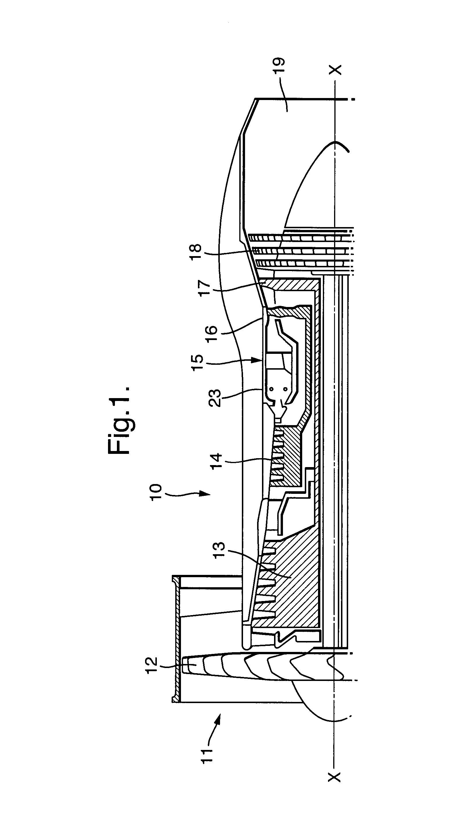
[0026]Referring to FIG. 1, a gas turbine engine is generally indicated at 10 and comprises, in axial flow series, an air intake 11, a propulsive fan 12, an intermediate pressure compressor 13, a high pressure compressor 14, a combustor 15, a turbine arrangement comprising a high pressure turbine 16, an intermediate pressure turbine 17 and a low pressure turbine 18, and an exhaust nozzle 19.

[0027]The gas turbine engine 10 operates in a conventional manner so that air entering the intake 11 is accelerated by the fan 12 which produce two air flows: a first air flow into the intermediate pressure compressor 13 and a second air flow which provides propulsive thrust. The intermediate pressure compressor compresses the air flow directed into it before delivering that air to the high pressure compressor 14 where further compression takes place.

[0028]The compressed air exhausted from the high pressure compressor 14 is directed into the combustor 15 where it is mixed with fuel and the mixture...


PUM


Abstract

A clearance control apparatus for controlling the clearance between a rotary assembly (17) and a casing (24) surrounding the rotary assembly (17) is disclosed. The clearance control apparatus comprises a temperature measuring device (34) to measure the temperature of a radially outer portion of the rotary assembly and a cooling arrangement (28) to cool the casing (24). A control system (36) is associated with the temperature measuring device (34) and the cooling arrangement (28) to control the extent of cooling of the casing (24). The extent of cooling is dependent upon the temperature of the aforesaid portion.

Description

[0001]This application claims priority to British Patent App'n Ser. No. 0609312.4, field 11 May 2006.FIELD OF THE INVENTION[0002]This invention relates to clearance control apparatus for controlling the clearance between rotary assemblies and the casing surrounding the rotary assemblies. More particularly, but not exclusively the invention relates to clearance control apparatus for controlling the clearance between the blade tips for turbine and the turbine casing.BACKGROUND OF THE INVENTION[0003]Gas turbine efficiency is affected by the clearance between the tip of a turbine blade and the turbine casing. Clearance needs to be minimised for maximum turbine efficiency.[0004]Turbine design calculations take into account all the related thermal expansions. The clearance is consequently set to avoid causing the tips of the blades to rub against the casing during certain manoeuvres. The design considerations ensure that the clearance is optimum at, for example, steady state operation. Ho...

Claims


Application Information

Patent Timeline
Patent Type & Authority Patents(United States)
IPC IPC(8): F01D11/24
CPCF01D11/24F05D2270/54F05D2270/303
Inventor SUTHERLAND, ROGER ABARNFATHER, COLIN RHOLT, JONATHAN EJACK, CHRISTOPHER DHILL, RALPH W
Owner ROLLS ROYCE PLC
Why Eureka
Try Eureka