Suspension system

a suspension system and suspension technology, applied in the direction of machines/engines, machine supports, liquid fuel engines, etc., can solve the problems of poor vibration isolation of elastomer bushings, affecting the stability of suspension systems, etc., to achieve high vibration isolation, constant linear dynamic stiffness, and enhance the effect of these properties

Inactive Publication Date: 2010-10-26
GENERAL ELECTRIC CO
View PDF21 Cites 22 Cited by
  • Summary
  • Abstract
  • Description
  • Claims
  • Application Information

AI Technical Summary

Benefits of technology

[0010]A laminated suspension element as described above acts like a spring and shows constant linear dynamic stiffness for either pure compression, pure shear or even a combination thereof. Typically, the suspension element will have a rather flat geometry which further enhances these properties compared to the cylindrical elastomer bushings. Thus, the suspension element provides high vibration isolation at any given load. In contrast to standard elastomer bushings, the dynamic behavior of the above described suspension element can be easily predicted and modeled.
[0011]According to an embodiment of the present invention, the suspension element has low dynamic stiffness and low dynamic damping to realize high vibration isolation by dynamically decoupling the apparatus relatively to its supporting structure. Therefore, the suspension element will typically have a dynamic stiffness in the range from about 10 kN / mm up to about 500 kN / mm and a dynamic damping loss in the range from about 1% to about 5%. To make the elastomer layer softer, specific molding patterns like longitudinal or lateral stripes extending through the elastomer layer may be provided. Typically, these specific molding patterns are formed as cavities and may cover up to 50% of the area of the elastomer layer. Typically, the area covered by these molding patterns is in the range from 1% to 50%, typically within 10% to 40% or 15% to 30% of the total area of the elastomer layer. The molding patterns can increase the elastomer expansion or deformation area under compression or shear load.
[0013]The additional displacement limiting element elements are fixed to the support and are not in contact with the apparatus during normal operation since the vibrational displacement of the apparatus during normal operation is smaller than the clearance. However, when high loads occur, e.g. normal short term high wind gusts or exceptional events like extreme wind gusts, emergency stops, cross-bar events or the like, the displacement limiting elements limit the lateral or vertical displacement of the apparatus. Typically, the displacement limiting elements will therefore have high dynamic stiffness and high dynamic damping to realize both displacement control and energy dissipation during extreme loads. Typically, the displacement limiting elements or displacement limiting elements have a dynamic stiffness in the range from about 100 kN / mm up to about 50000 kN / mm and a dynamic damping loss in the range from about 5% to about 25%. Typically, the stiffness curve of the displacement limiting elements is non-linear.

Problems solved by technology

Because dynamic forces from machinery correspond to a discrete force spectrum described by meshing frequencies, the noise spectrum related can also be discrete in nature and result in tonal noise components.
However, cylindrical elastomer bushings have several disadvantages, namely that they are highly non-linear elements and, therefore, become dynamically hard as steel if high loads are applied.
Furthermore, elastomer bushings exhibit poor vibration isolation over the entire frequency range due to their cylindrical shape and their dynamic stiffness increase with frequency.
Moreover, the vibration isolation ability of elastomer bushings rapidly decreases with environmental temperature.
A further drawback of standard cylindrical elastomer bushings is that they only operate providing low dynamic stiffness and hence some vibration isolation potential along the radial axis direction and allow only very small lateral displacement, thus enabling only very low isolation on the other axis because of typically high radial dynamic stiffness incompatible with vibration isolation.
Therefore, a conflict exists between vibration isolation requiring very soft mounts to provide vibration isolation for noise control purpose and very hard mounts that can sustain high loads and allow only small displacements of the machinery.

Method used


Image

  • Suspension system
  • Suspension system
  • Suspension system

Examples


Embodiment Construction

[0024]Reference will now be made in detail to the various embodiments of the invention, one or more examples of which are illustrated in the figures. Each example is provided by way of explanation of the invention, and is not meant as a limitation of the invention. For example, features illustrated or described as part of one embodiment can be used on or in conjunction with other embodiments to yield yet a further embodiment. It is intended that the present invention includes such modifications and variations.

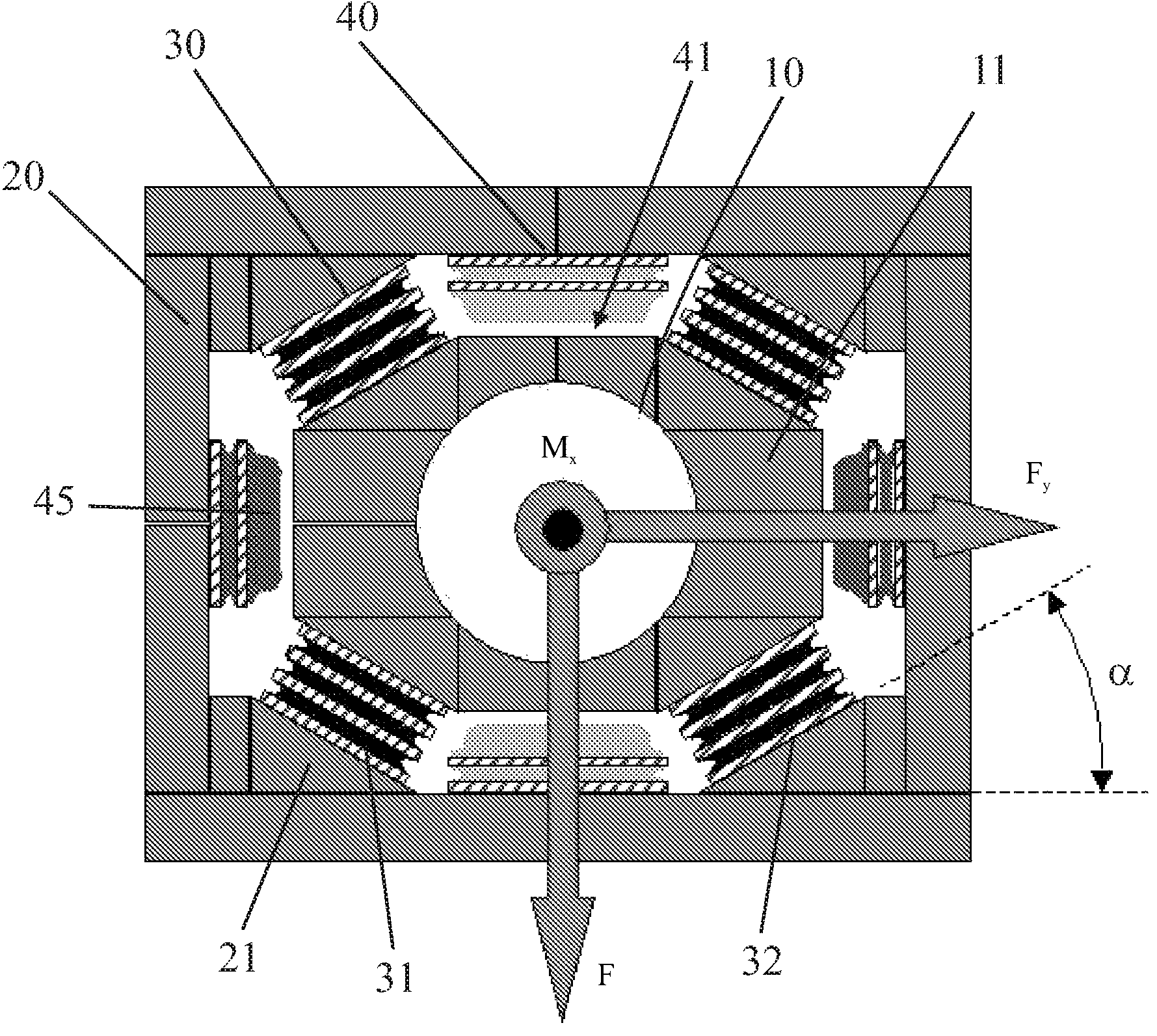
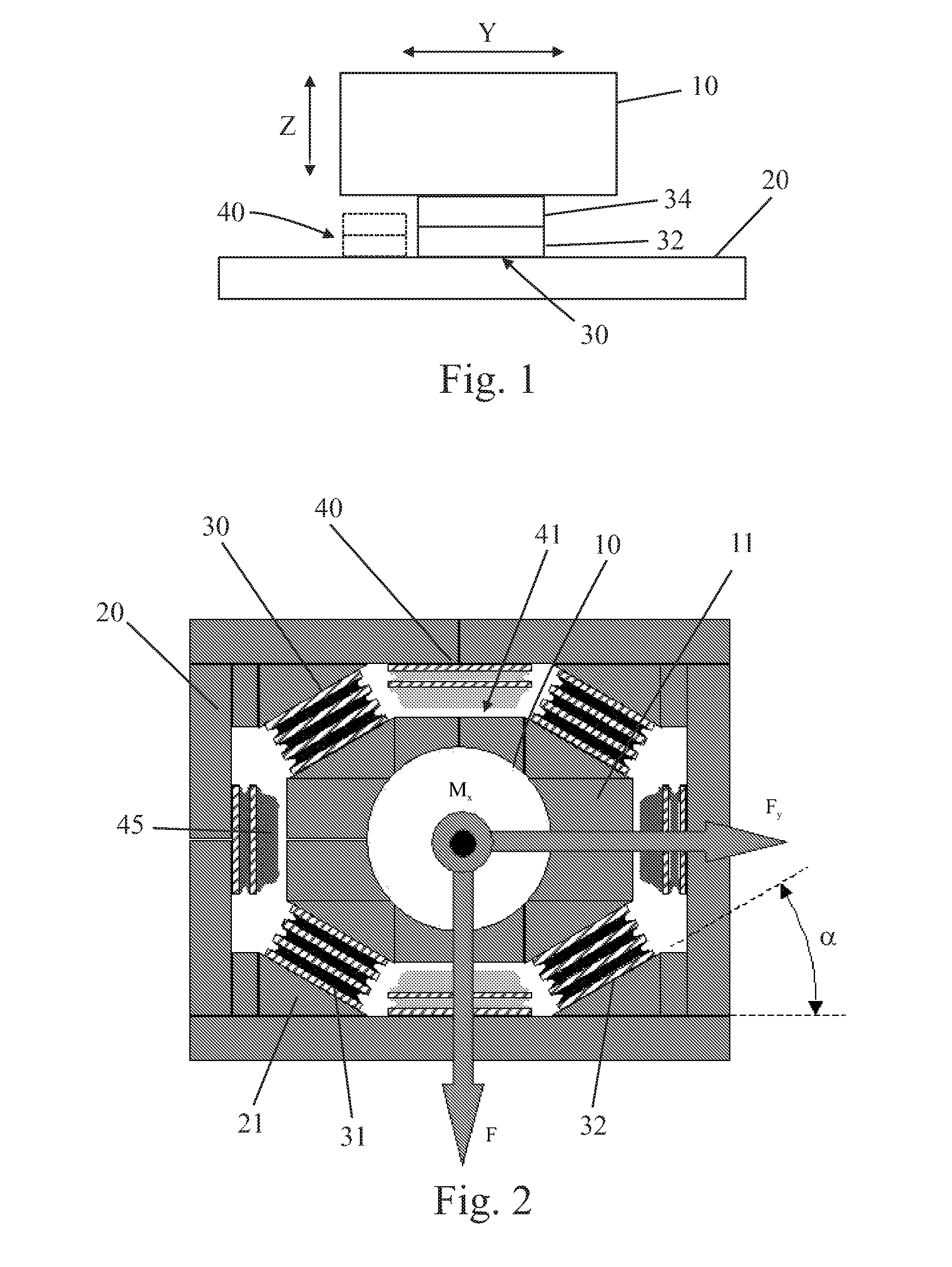
[0025]FIG. 1 is a schematic view of a suspension system according to an embodiment of the present invention. Therein, a suspension element 30 is mounted between an apparatus 10 and a support 20. The apparatus 10 vibrates, i.e. is displaced, in Z- as well as in Y-direction as indicated by the arrows. The suspension element 30 dynamically decouples the apparatus 10 from the support 20 so that the vibrations of the apparatus are not or only to a small degree transferred to support...


PUM

PropertyMeasurementUnit
frequencyaaaaaaaaaa
angleaaaaaaaaaa
angleaaaaaaaaaa

Abstract

A suspension system for suspending an apparatus is disclosed. The suspension system includes at least one suspension element mountable between the apparatus and a support. The at least one suspension element includes a laminate material having at least one metal layer and at least one elastomer layer laminated thereon.

Description

FIELD OF THE INVENTION[0001]The present invention relates to a suspension system and to a wind turbine comprising the suspension system.BACKGROUND OF THE INVENTION[0002]Noise emission from technical installations, particularly power systems, is a safety and environmental concern. Legislation dictates the admissible sound pressure level that a noise source in a certain location may continuously make so that reduced noise emission is a key requirement for low impact environmental integration. Regulations governing these levels vary currently from country to country. In Europe, European Directives 2000-194-EC and 2002-49-EC provide standards. In Germany, the standard values are based on VDI standard 2058, and were adopted by the Technical Directive on Noise Abatement prescribed by law. The maximum allowable values depend on the character of the surroundings and the time of day. For example, 65 dB(A) are allowed in a prevailing industrial surrounding during the day, whereas only 35 dB(A...

Claims


Application Information

Patent Timeline
Patent Type & Authority Patents(United States)
IPC IPC(8): F03D11/00F16F1/36F16F15/08
CPCF03D11/00F16F1/40F16F15/08F05B2260/96F05B2280/4004F05B2280/6003F05C2225/02F05C2253/04F16F2230/007Y02E10/722Y02E10/726F05B2260/964F03D80/00Y02E10/72
Inventor BONNET, LAURENT
Owner GENERAL ELECTRIC CO
Why Eureka
Try Eureka