Linearly expanding spine cage for enhanced spinal fusion

a spine cage and spine technology, applied in the field of linear expansion of the spine cage, can solve the problems of increasing the fixation force, and achieve the effects of reducing pain, early mobilization of patients, and improving function

Active Publication Date: 2010-10-26
HOWMEDICA OSTEONICS CORP
View PDF66 Cites 305 Cited by
  • Summary
  • Abstract
  • Description
  • Claims
  • Application Information

AI Technical Summary

Benefits of technology

[0014]An aspect of the invention comprises a linearly expanding spine cage (LEC) comprising two halves joined along a common longitudinal axis to form a cylinder with a minimized diameter in its unexpanded state that is equal to the diameter of an insertion groove cut in adjacent vertebral bodies. The LEC is thus conformably engaged between the endplates of adjacent vertebra to effectively distract the intervertebral area, restore space for neural elements, stabilize the motion segment and eliminate pathologic segmental motion. The LEC enhances spinal arthrodesis by creating a rigid spine segment.
[0015]The LEC provides a significant advantage by enabling a comparatively large quantity of bone growth enhancing agents to be contained within its interior and communicated directly to adjacent bone over a maximized surface area due to a perforated design with apertures dispersed through multiple rows of corrugations, ridges, points, troughs or other features for bone engagement provided on radial surfaces of LEC halves. Importantly, this results in fixation forces greater than adjacent bone and soft tissue failure forces.
[0016]By expanding linearly (vertically, along the vertical axis of the entire spine) rather than uniformly (which would take up more space inside the vertebral body surfaces), the cage height increases to hold the vertebrae, while the width remains stable so as to decrease impingement upon a second cage, or upon soft tissue structures in the immediate vicinity (neural elements).
[0018]The clinical goals of the LEC and method for its insertion reduce pain, improve function, and permit early mobilization of the patient after fusion surgery. Since the LEC pullout forces are greater than vertebral body failure forces, patients can mobilize more quickly than was previously possible. Once healing (fusion or arthrodesis) does occur, the implants become incorporated and their role becomes quiescent.
[0019]The present LEC provides more internal to external graft bone space exposure, easier insertion, less risk of insertional damage to nerve roots and other tissue, and thus a substantially improved immediate and long term result. The specialized exterior on the outside of the LEC seeks to balance multiple projections, tines, or other bone engaging features that will hold firmly adjacent bone to prevent prosthetic extrusion, while being sufficiently rounded so as to avoid injuring nearby nerve or vascular structures. Bone ingrowth is encouraged by the perforated design of the LEC and the exterior corrugations that greatly increase the surface area of the LEC that conformably engages adjacent vertebral bone. By avoiding a square or rectangular configuration, the LEC is less prone toward subsidence.

Problems solved by technology

Importantly, this results in fixation forces greater than adjacent bone and soft tissue failure forces.

Method used


Image

  • Linearly expanding spine cage for enhanced spinal fusion
  • Linearly expanding spine cage for enhanced spinal fusion
  • Linearly expanding spine cage for enhanced spinal fusion

Examples


Embodiment Construction

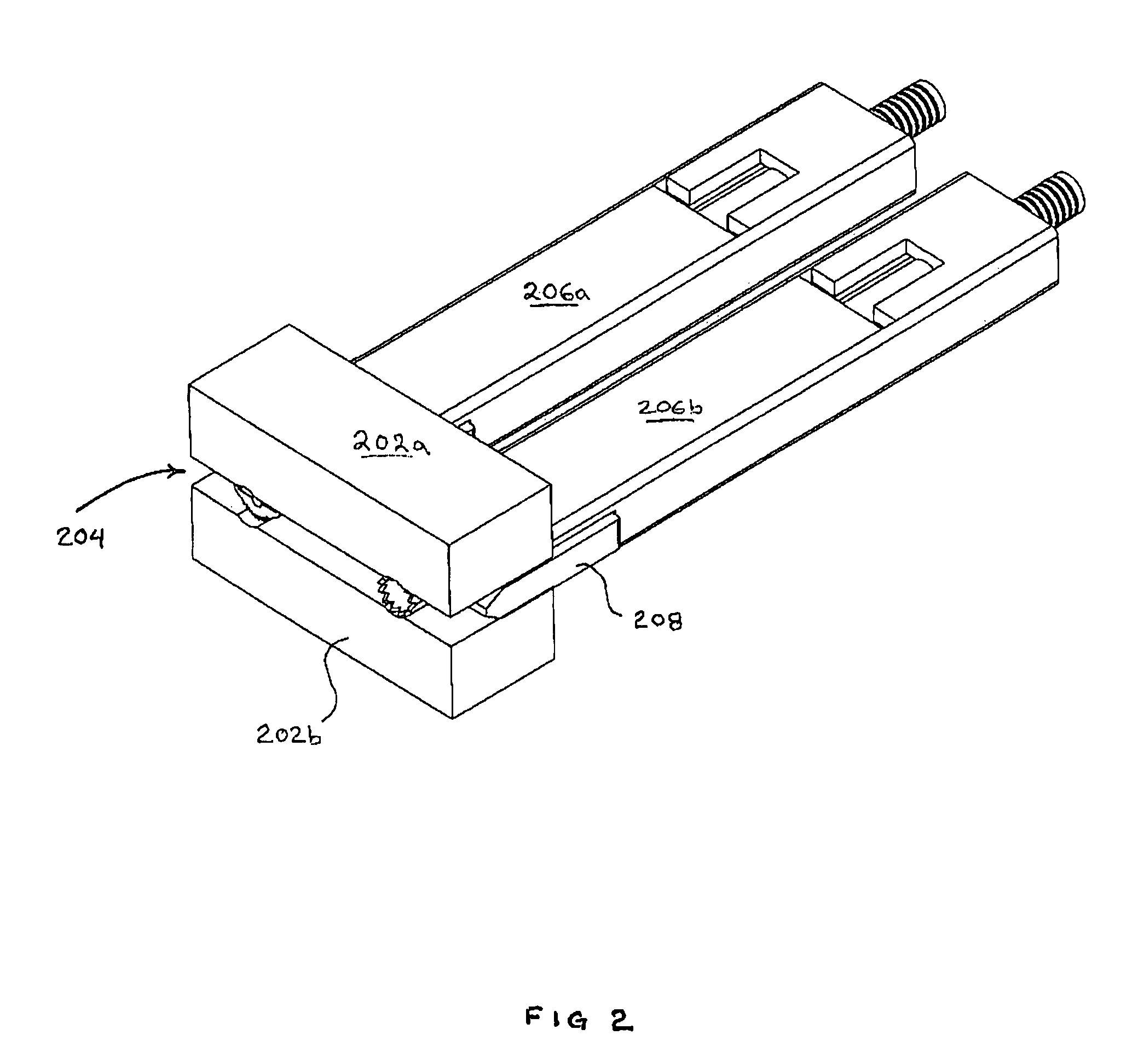
[0034]Referring to FIG. 2, vertebral segments 202a and 202b are shown with an 8 mm gap representing an average intervertebral space 204. The vertebral segments 202a and 202b are shown as blocks for clarity. A complete discectomy is performed prior to the insertion of the LEC.

[0035]As is well understood by one skilled in the art, the intervertebral disc occupying space 204 will be removed using standard techniques including rongeur, curettage, and endplate preparation to bleeding subchondral bone. The posterior longitudinal ligament will be divided to permit expansion of the intervertebral space.

[0036]The intervertebral space 204 will be distracted to 10 mm using a rotating spatula (Not shown. This is a device that looks like a wide screw driver that can be placed into the disc space horizontally and turned 90 degrees to separate the endplates).

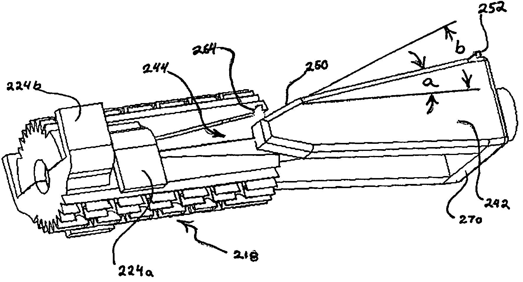
[0037]Referring to FIG. 2 through FIG. 5, one or two 10 mm cage cannulas 206 are inserted between the vertebral segments 202a and 202b. It wi...


PUM

PropertyMeasurementUnit
diameteraaaaaaaaaa
widthaaaaaaaaaa
intervertebral body forceaaaaaaaaaa

Abstract

A linearly expanding spine cage has a minimized diameter in its unexpanded state that is equal to the diameter of an insertion groove cut into adjacent vertebral bodies. The cage conformably engages between the endplates of adjacent vertebrae to effectively distract the disc space, widen neuroforamina, stabilize the motion segments and eliminate pathologic spine motion. Angular deformities can be corrected, and natural curvatures maintained. The cage enhances spinal arthrodesis by creating a rigid spine segment. Expanding linearly (vertically, along the vertical axis of the adjacent spine) rather than uniformly, the cage height increases and holds the vertebrae with fixation forces greater than adjacent bone and soft tissue failure forces. Stability is thus achieved immediately, enabling patient function by eliminating painful motion. The cage width remains stable, so as to decrease impingement upon a second cage, or upon soft tissue structures in the immediate vicinity, including neural or vascular elements.

Description

RELATED APPLICATIONS[0001]This application is a divisional of application Ser. No. 11 / 202,725, filed Aug. 12, 2005, now U.S. Pat. No. 7,722,674 which is incorporated herein in its entirety by reference and from which priority is claimed.TECHNICAL FIELD[0002]The present invention relates generally to the field of medical devices for stabilizing the vertebral motion segment. More particularly, the present invention relates to a linearly expanding spine cage (LEC), and a method for providing improved spinal intervertebral body distraction and fusion.BACKGROUND ARTInability to Expand and Distract Endplates[0003]Referring to FIG. 1, a conventional spine cage or implant 101 is characterized by a cylindrical body comprising a plurality of threads 104 provided on the exterior surface for contact with adjacent vertebral segments or endplates 102a and 102b, which are shown as blocks for clarity. Conventional spine cage 101 is typically inserted in tandem between vertebral segments 102a and 10...

Claims


Application Information

Patent Timeline
Patent Type & Authority Patents(United States)
IPC IPC(8): A61F2/44
CPCA61F2/446A61F2/4611A61B2017/0256A61F2002/2817A61F2002/30153A61F2002/30507A61F2002/3055A61F2002/30616A61F2002/30784A61F2002/30841A61F2002/30878A61F2002/30975A61F2002/4475A61F2002/448A61F2002/4627A61F2220/0025A61F2230/0019A61F2310/00023A61F2310/00796A61F2310/00976A61F2002/30593
Inventor GROTZ, R. THOMAS
Owner HOWMEDICA OSTEONICS CORP
Why Eureka
Try Eureka