Hybrid solar thermal chimney

a solar thermal and hybrid technology, applied in wind motors with solar radiation, electric generator control, machines/engines, etc., can solve the problems of large solar collectors that are expensive to build, prior art requires an expensive buffer, and large tall structures are required

Inactive Publication Date: 2010-10-26
LE JOHN O +2
View PDF51 Cites 55 Cited by
  • Summary
  • Abstract
  • Description
  • Claims
  • Application Information

AI Technical Summary

Problems solved by technology

A problem with the prior art is that these large solar collectors are expensive to build and must take up a large section of land.
Often times the prior art requires an expensive buffer such as a battery bank to even out energy flow between sunny and cloudy days, or a thermal storage such as a molten salt tank to even out the energy flow during intermittent cloudiness within a day.
Thus a large tall structure is required and the cost of construction makes the arrangement impractical.
When the solar input into the solar thermal receiver fluctuates such as from temporary misalignment of heliostats (control or mechanical glitches), or intermittent cloudiness, or rapidly varying grid electrical power demand, a single spool (mechanically coupled compressor and turbine) pure solar Brayton cycle is susceptible to turbine instability or receiver burnout.
As a result, in practice, heliostats are often taken off line, generating no energy, when conditions are less than optimal.
This make many prior art arrangements either expensive to operate or unreliable.
The land area adjacent to the central receiving tower in a heliostat field is thus wasted.
Prior art arrangements have failed to be able to provide enough energy benefit to offset the cost of the land used and the structure required.

Method used


Image

  • Hybrid solar thermal chimney
  • Hybrid solar thermal chimney
  • Hybrid solar thermal chimney

Examples


Embodiment Construction

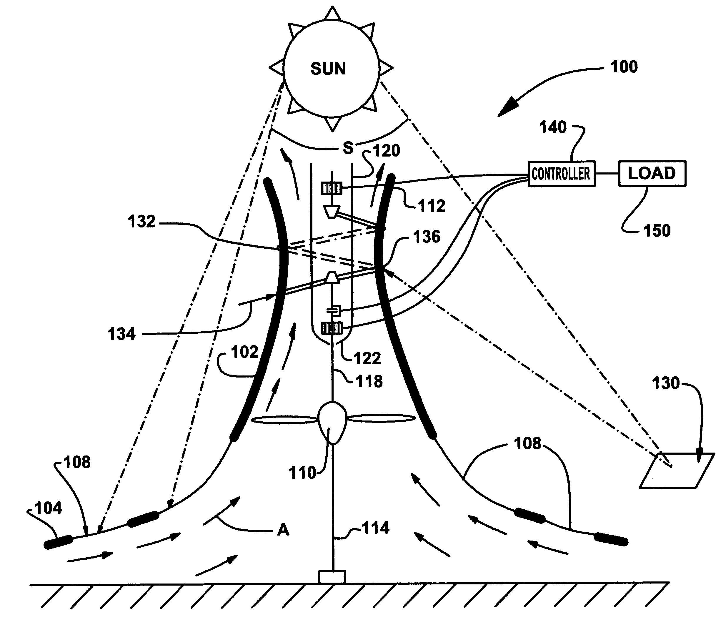
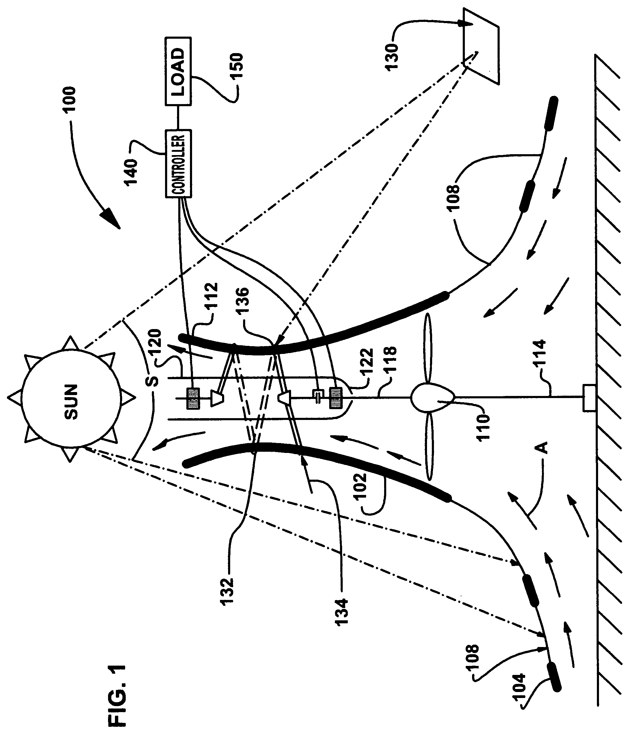
[0014]FIG. 1 shows an overall view of the system 100. The system 100 includes a chimney shell 102. The chimney includes a large flared base 104 that is held off the ground to allow for intake air to flow in. Air flow is indicated by arrows ‘A’. Air flows upward through the chimney shell 102 driven by solar heating that occurs within the chimney shell 102. Within the chimney shell 102 air can be heated by solar energy ‘S’ part of which can pass through window portions 108 of the chimney shell 102. Ideally the chimney shell 102 will primarily be glass or similar material that will allow for a maximum amount of net energy transfer into the chimney shell 102. The flared base portion 104 should ideally be almost entirely transparent. Air travels up through the chimney shell 102 and as it does so it powers the wind turbine 110 located within the chimney shell 102. The air then passes out the top end 112 of the chimney shell 102.

[0015]The first energy system of the chimney shell 102 is pow...


PUM


Abstract

A solar power arrangement for converting solar energy into electricity comprising; a solar chimney, the chimney having a flared base spaced from the ground the chimney including a transparent surface to allow solar energy to heat air within the solar chimney. A first air turbine drives a first generator, and the chimney including an exhaust. The first air turbine drives an air compressor and wherein the compressor includes an ambient air intake and a plurality of pipes for receiving compressed attached to the solar chimney. A plurality of heliostats focus solar energy on the pipes to heat the compressed air contained therein and a second turbine driven by expansion of the compressed air wherein the second turbine drives a second generator.

Description

CROSS REFERENCES TO RELATED APPLICATIONS[0001]NoneSTATEMENT AS TO RIGHTS TO INVENTIONS MADE UNDER FEDERALLY SPONSORED RESEARCH AND DEVELOPMENT[0002]Not ApplicableBACKGROUND OF THE INVENTION[0003]1. Field of the Invention[0004]This invention relates to deriving power from solar sources.[0005]2. Brief Description of Prior Art[0006]U.S. Pat. No. 5,300,817 is one prior art attempt to collect solar power using a chimney effect. The housing of the device is constructed partially of glass such that air heated by the sun rises within a chimney. As the air rises in the chimney it can drive a turbine. A problem with the prior art is that these large solar collectors are expensive to build and must take up a large section of land. Therefore it is important to derive the maximum amount of energy from as compact and economical structure as possible, power interruption is also an important consideration. It is also important that a solar generator be able to produce energy in a range of condition...

Claims


Application Information

Patent Timeline
Patent Type & Authority Patents(United States)
IPC IPC(8): F03D9/00H02P9/04F03B13/00F03B13/10
CPCF03D9/007F03G6/045F05B2240/131F05B2260/24Y02E10/465Y02E10/725F03D9/25F03D9/28F03D9/37Y02E10/46Y02E10/72Y02E10/728Y02E60/16
Inventor LE, JOHN O.LE, CHRISTOPHER M.LE, THOMAS T.
Owner LE JOHN O
Why Eureka
Try Eureka