
Gradient index lens for microwave radiation

a technology of gradient index and microwave radiation, applied in the field of microwave lenses, can solve problems such as beam bending or beam redirection, and achieve the effect of less attenuation of microwave radiation and easy construction

Inactive Publication Date: 2010-10-26
TOYOTA MOTOR CO LTD +1
View PDF19 Cites 11 Cited by
  • Summary
  • Abstract
  • Description
  • Claims
  • Application Information

AI Technical Summary

Benefits of technology

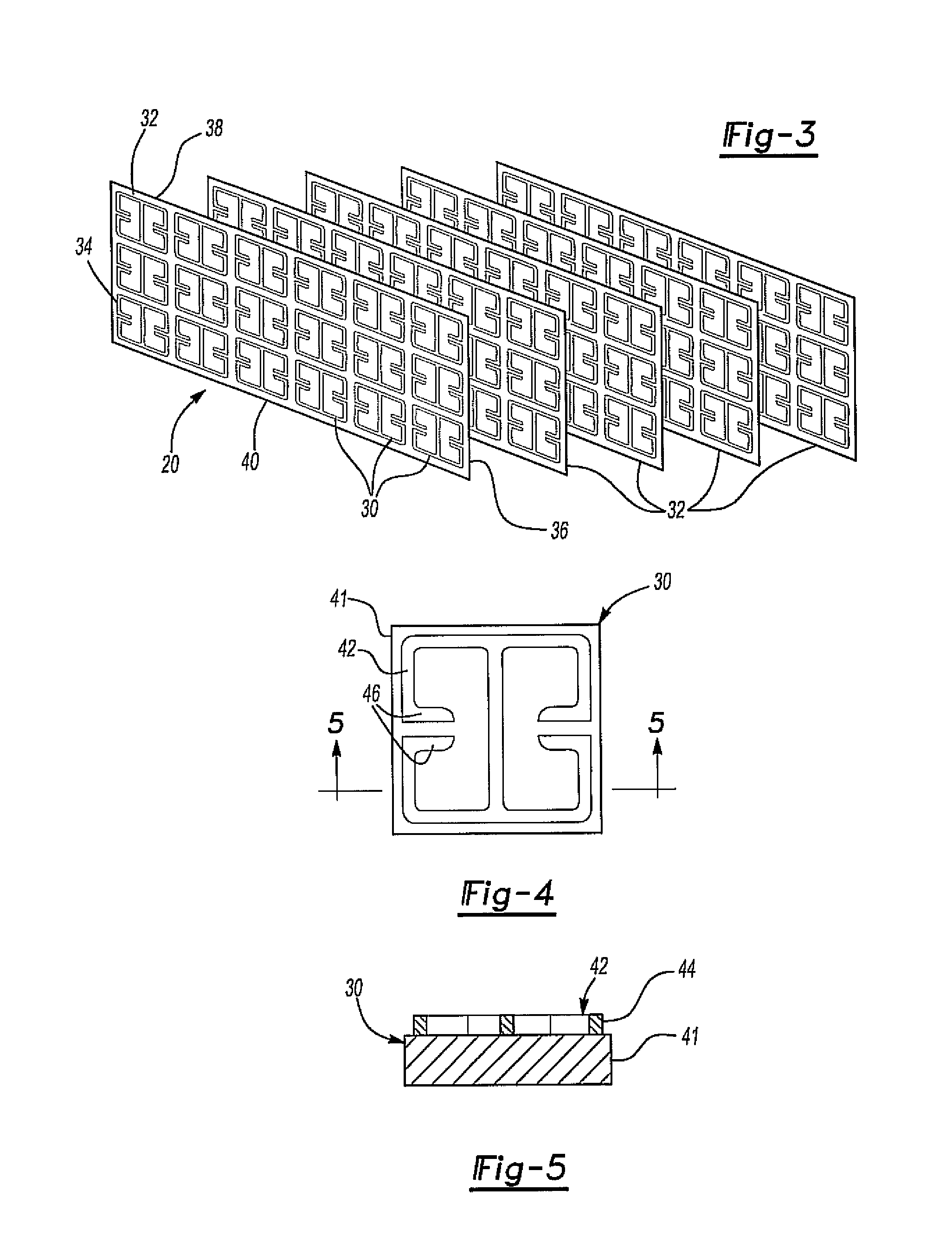
The present invention provides a gradient index lens for microwave radiation that overcomes the disadvantages of previously known devices. The lens comprises a plurality of electronic inductive capacitive resonators arranged in a planar array with spaced apart edges. The resonators have their own resonant frequency, which can vary between the edges of the array to achieve beam focusing or bending. Each resonator includes a conductive pattern on a nonconductive substrate that responds to incident microwave radiation as an LC resonant circuit. The length of the conductive pattern can be adjusted to change the resonant frequency. The use of positive index material for the resonators results in less attenuation of the microwave radiation passing through the lens.

Problems solved by technology

Conversely, the variation of the resonant frequency in a linear fashion from one edge and to its spaced apart edge will result in beam bending or beam redirection.

Method used


Image

  • Gradient index lens for microwave radiation
  • Gradient index lens for microwave radiation
  • Gradient index lens for microwave radiation

Examples


Embodiment Construction

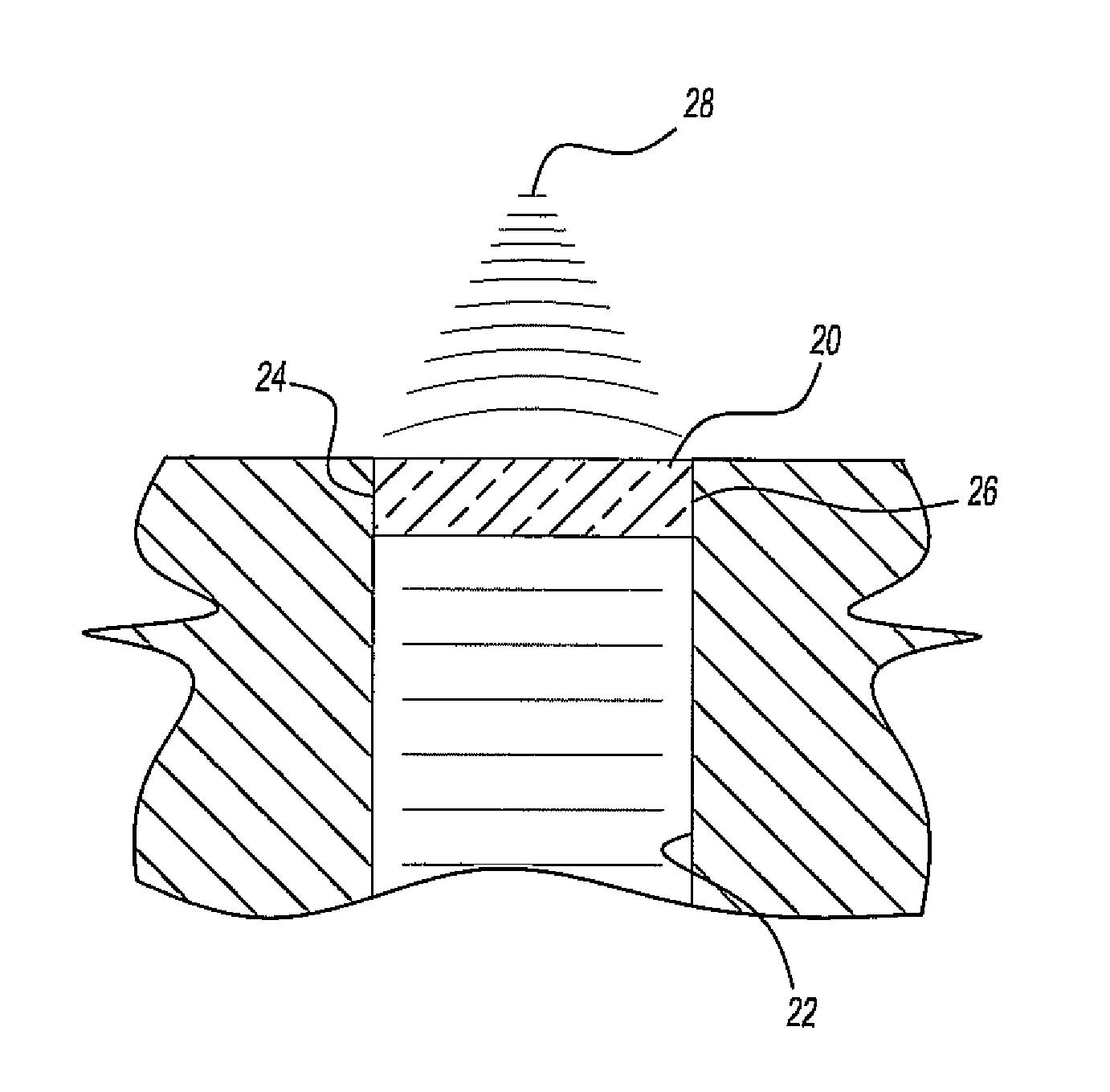
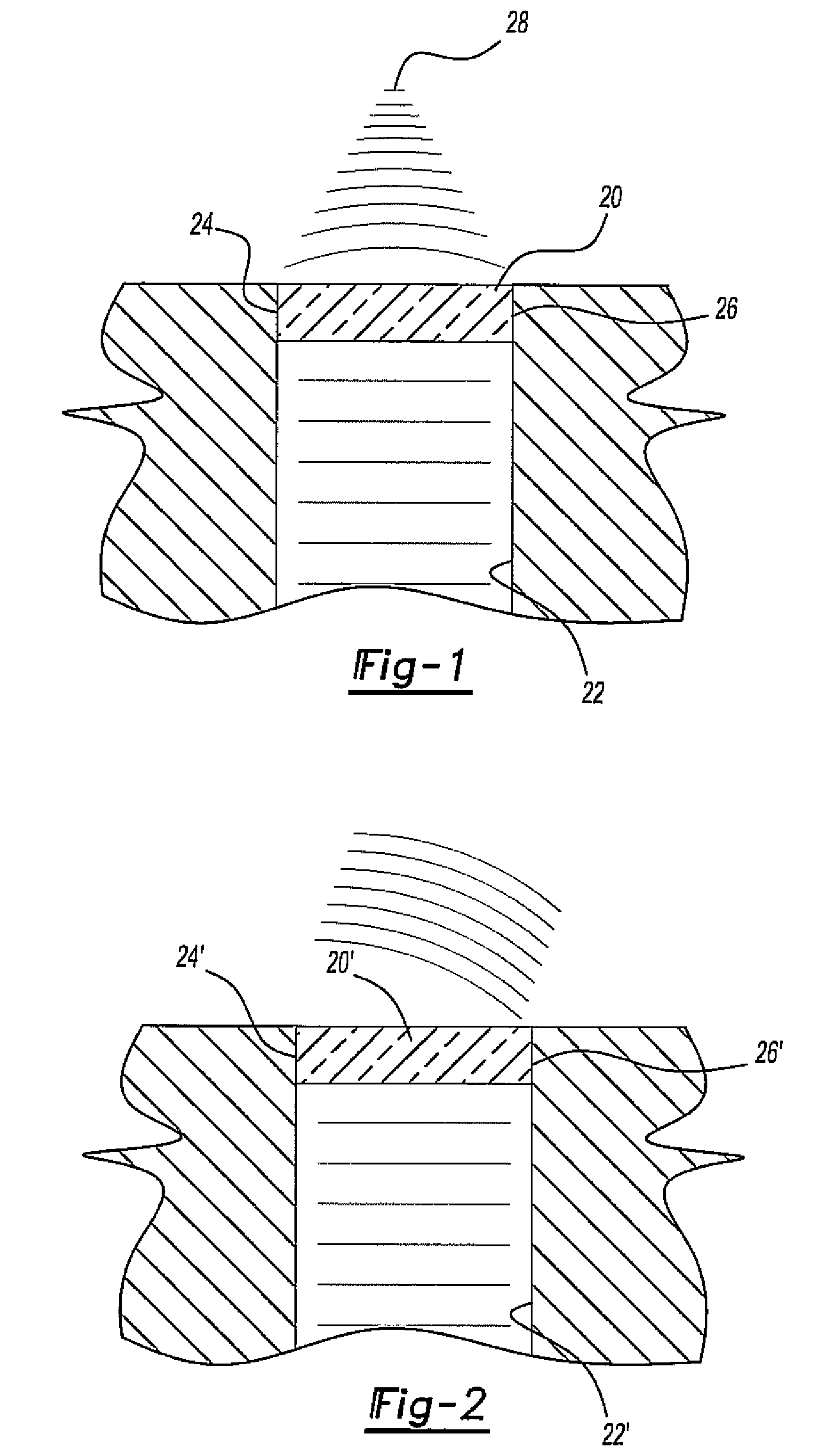
[0025]With reference first to FIG. 1, a gradient index lens 20 for microwave radiation is illustrated positioned at the end of a microwave guide 22. In a fashion that will be subsequently described in greater detail, the refractive index of the lens 20 varies in a parabolic fashion from one side edge 24 and to its other side edge 26. Consequently, assuming that the incident microwave radiation, i.e. radiation in the range of 300 megahertz to 300 gigahertz, impinges upon the lens 20, the refraction of the lens 20 will focus the radiation at point 28.

[0026]With reference now to FIG. 2, a modified form of the gradient index lens 20′ is illustrated in which the index of refraction for the lens 20′ varies linearly from one side edge 24′ and to the other side edge 26′ of the lens 20. Such a configuration for the lens 20′ results in bending or redirection of the microwave beam passing through the microwave guide 22′ and through the lens 20′.

[0027]The microwave lens 20 may, of course, be us...


PUM


Abstract

A gradient index lens for microwave radiation. The lens includes a plurality of electric field coupled resonators wherein each resonator has a resonant frequency. The resonators are arranged in a planar array having spaced apart side edges and spaced apart top and bottom edges. The resonant frequency of the resonators varies between at least two of the spaced edges of the array in accordance with the desired properties of the lens.

Description

BACKGROUND OF THE INVENTION[0001]I. Field of the Invention[0002]The present invention relates to microwave lenses and, more particularly, to a gradient index microwave lens which utilizes a plurality of electronic inductive capacitive resonators arranged in a planar array.[0003]II. Description of Related Art[0004]The field of metamaterials continues to grow in popularity. Such metamaterials exhibit properties in response to electromagnetic radiation which depends on the structure of the metamaterials, rather than their composition.[0005]Most of the interest in metamaterials, however, has focused on metamaterials which exhibit a negative refractive index. Such a negative refractive index is possible where both the permittivity as well as the permeability of the material is negative.[0006]One difficulty with negative index metamaterials, however, is that they are difficult to construct and also result in high attenuation of incident radiation. Furthermore, none of the previously known...

Claims


Application Information

Patent Timeline
Patent Type & Authority Patents(United States)
IPC IPC(8): H01Q15/02
CPCH01Q1/3233H01Q19/06H01Q19/08
Inventor JUSTICE, BRYAN J.NGUYEN, VINH N.SMITH, DAVID R.YONAK, SERDAR H.
Owner TOYOTA MOTOR CO LTD
Learn More