
Method for light propagation time measurement

a technology of light propagation time and measurement method, which is applied in distance measurement, instruments, surveying and navigation, etc., can solve the problems of difficult to determine the exact point of incidence, still more difficult, and the rise of sending leds

Active Publication Date: 2010-10-26
REIME GERD
View PDF10 Cites 5 Cited by
  • Summary
  • Abstract
  • Description
  • Claims
  • Application Information

AI Technical Summary

Benefits of technology

"The invention provides a method for measuring the time it takes for light to propagate through a camera or other optical devices. This is done by using a combination of light sources and compensation light sources, which helps to eliminate the effects of reflection and other extraneous light. The method also uses a synchronous demodulator to detect and measure the light propagation time, which is then used to determine the distance between the light source and the object or receiver. The invention has several advantages, including high sensitivity, good propagation time measurement at close range, and no temperature effects. The method can be used in cameras and other optical devices to provide accurate and efficient distance measurement."

Problems solved by technology

Hereby, the following problem with the state of the art occurs: If one applies a pulsed voltage to a light emitting diode, then it lights up at the rhythm of this applied voltage.
In order to measure the distance of the reflecting object, the use of a light propagation time measurement between the sent and the received signal is of course possible, but in the case of the above mentioned very small received current in the photodiode, it is very difficult to determine the exact point of incidence.
Making it still more difficult is the fact that the signal entering the photodiode or the amplifier connected thereto does not produce the flank steepness with which it was sent.
The sending LED also has a noticeable rise time, but this however, is orders of magnitude below the low-pass characteristic of low cost photodiodes.
The process of detecting the precise moment of incidence of the reflection signal thus causes substantial difficulties and so many patent applications are concerned with improving the process of detecting the exact moment of incidence of the reflection signal.
Adding still more to the difficulty is the problem of ambient light, temperature and the respective reflection factor of the object being measured.
Even if the time point of the received signal were to be specified precisely, a further unwanted effect arises.

Method used


Image

  • Method for light propagation time measurement
  • Method for light propagation time measurement
  • Method for light propagation time measurement

Examples


Embodiment Construction

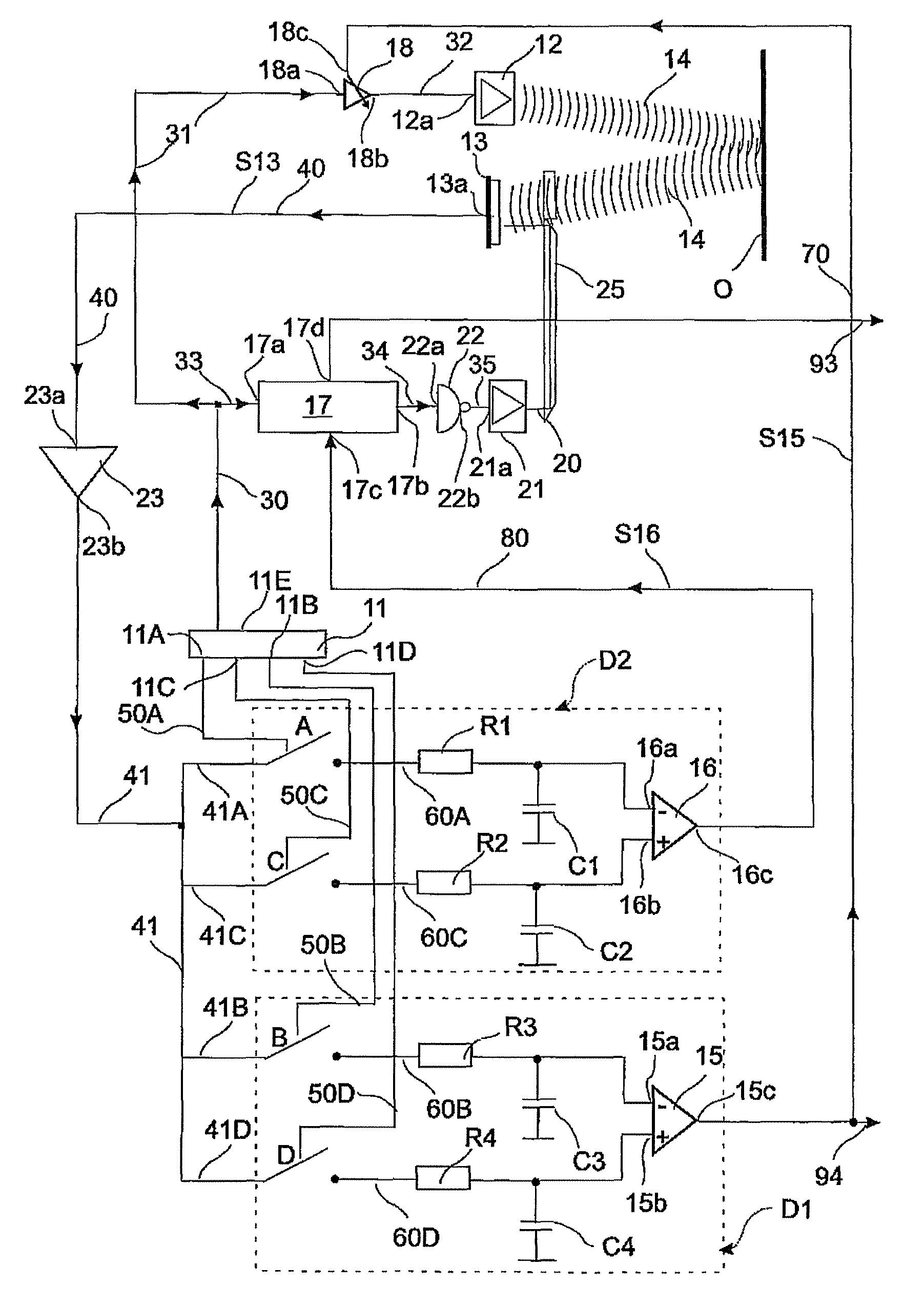
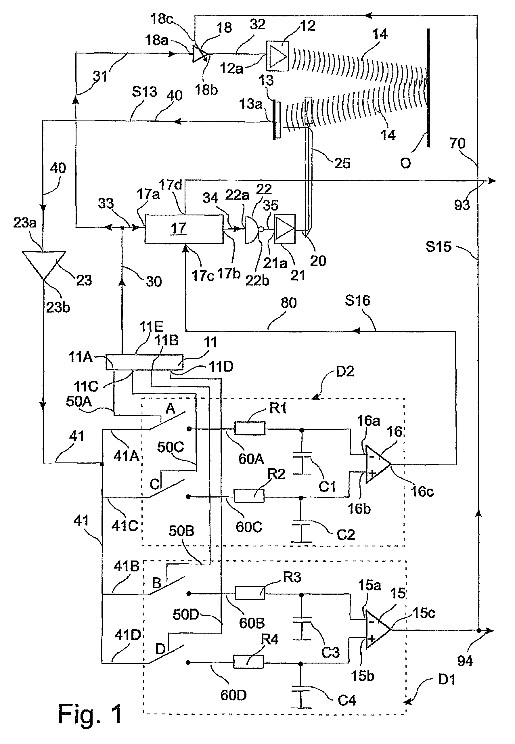
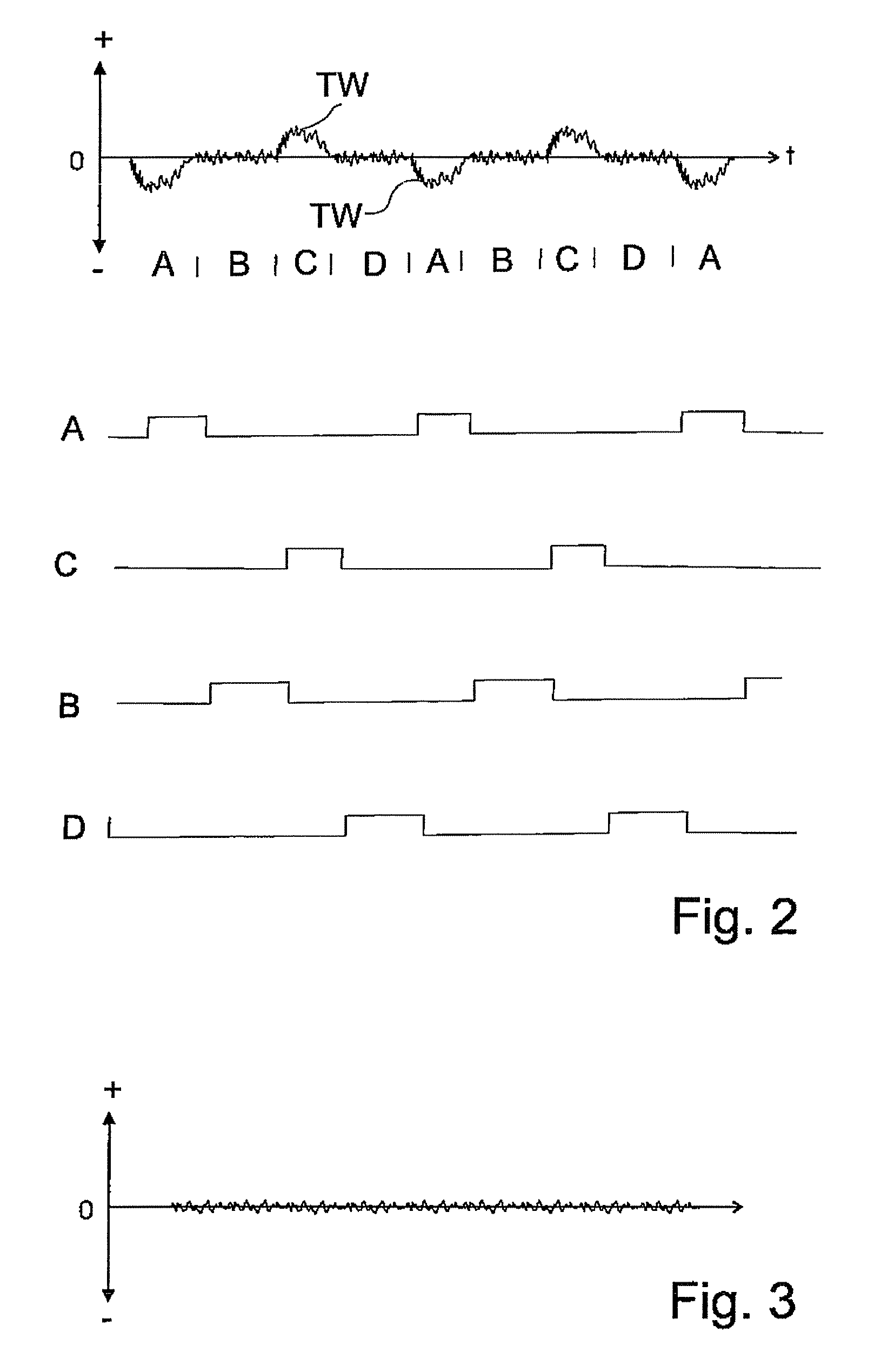
[0044]The invention is now described in more detail in exemplary manner with reference to the accompanying drawings. Nevertheless, the exemplary embodiments are merely examples which are not intended to restrict the inventive concept to a certain arrangement.

[0045]Before the invention is described in detail, it should be pointed out that it is not restricted to the particular components of the circuit or the particular method steps since these components and methods can vary. The terms used here are merely intended to describe special embodiments and are not used in a restrictive manner. If, in addition, the singular or indefinite article is used in the description and in the Claims, this also refers to a plurality of these elements as long as the general context is not unambiguously making something else clear.

[0046]The invention enables a distance measurement to be made which permits of an accurate light propagation time measurement that is free of extraneous light problems, indep...


PUM


Abstract

Disclosed is a method and a device for light propagation time measurement, wherein a light signal is transmitted from at least one transmitter into a light path via a retroreflective object to a receiver for detecting the alteration of the first signal, presence, and / or distance of the object, the received signal being determined from the path and compared with a second signal produced without the light path to achieve a comparison value, which regulates amplitude values of the transmitted signal and / or of the second signal, a clock change signal corresponding to the light propagation time between received signal and second signal is detected cyclically, a difference value being determined by comparing change signals between received signal and second signal , the difference value being altered by means of a phase shifter , delay of the phase shifter that occurred given a minimal difference value determining the light propagation time.

Description

CROSS REFERENCE TO RELATED APPLICATIONS[0001]The present application claims the priority of the German Patent Applications 10 2005 036 354.7 filed on 29 Jul. 2005, and 10 2005 045 993.5 filed on 27 Sep. 2005, the disclosure whereof is hereby expressly incorporated into the subject matter of the present application by reference.TECHNICAL FIELD OF THE INVENTION[0002]The invention relates to a method and a device for light propagation time measurement.BRIEF DISCUSSION OF RELATED ART[0003]The distance of a reference object relative to other objects has to be determined in many fields of application. One such field of employment is, above all, that of camera systems, e.g. in the automotive field too or in the field of robotics.[0004]Hereby, the following problem with the state of the art occurs: If one applies a pulsed voltage to a light emitting diode, then it lights up at the rhythm of this applied voltage. A reflecting object can reflect the radiated light power to a photodiode that i...

Claims


Application Information

Patent Timeline
Patent Type & Authority Patents(United States)
IPC IPC(8): G01C3/08G01S17/10G01S7/4865H04N23/75
CPCG01S7/487G01S17/10G01S7/4865
Inventor REIME, GERD
Owner REIME GERD
Learn More