In-flight transceiver and locator system

a locator system and transceiver technology, applied in the field of transceiver systems, can solve the problems of not providing real-time data updates, system size is not typically small enough to fit inside the cockpit of the aircraft, and current attempts at in-flight locator systems are bulky, etc., to achieve the effect of quick sending and receiving messages

Active Publication Date: 2010-10-26
COMTECH MOBILE DATACOM CORP
View PDF32 Cites 9 Cited by
  • Summary
  • Abstract
  • Description
  • Claims
  • Application Information

AI Technical Summary

Benefits of technology

[0010]There is also a method for communicating between an in-flight transceiver system and a ground unit. The method includes providing at least one of the embodiments of the in-flight transceiver system described above and sending a communications packet over a communications channel that is not previously allocated or predetermined. In some embodiments, the transceiver software determines the receive channel by searching a prioritized list of channels that have been configured as part of a provisioning process. In embodiments that utilize this method of channel selection, there is a transmit frequency associated with the configured receive channel. Additionally or alternatively, in some embodiments, the transceiver software determines the receive channel by searching the entire configured frequency space in frequency steps. These frequency steps are typically configurable. If using this method to select the channel, the transceiver listens on the receive channel for instructions, e.g., configuration messages, on how to set the correct transmit frequency. This feature provides for great versatility in the adaptability of the system. Once a channel is identified, a first packet is transmitted from the ground unit to the in-flight transceiver system. In some embodiments the reverse occurs; once a channel is identified a first packet is transmitted from the in-flight transceiver system to the ground unit. The size of the packet transmitted is typically small, allowing for maximal transmission over minimal bandwidth. Next, a second packet is transmitted, either before an acknowledgement is returned for the first packet or without the sending party requesting successful receipt of the first communications packet. While in some versions, the second packet is sent over the same channel as the first packet, in some versions the second packet is sent over a channel that is not the same channel used by the first packet. Transmitting the packets over different channels results in increased system robustness because even if a packet on one channel is intercepted, the second packet avoids detection, thus preventing re-construction of the sent message. As the number of packets transmitted increases, the robustness of the system increases because packets are spread over several channels. By repeating these steps, exceptionally high rates of data transmission can be achieved. Test results have shown that the receipt rate of the transmitted packets by intended recipients is high, with a success rate on the order of 90% or more. In contrast, other systems that employ an acknowledgement request suffer unnecessary and burdensome loads on communications bandwidth that causes system inefficiencies. Beneficially, in embodiments of the present invention, acknowledgement requests and / or receipts are omitted.
[0014]In some implementations, the in-flight transceiver system provides beyond line of sight (BLOS) communications. Additionally, the in-flight transceiver system provides access to the Army Battle Command System (ABCS), which employs fixed and / or semi-fixed installations and mobile networks, and Global Command and Control System-Army (GCCS-A) that are otherwise unavailable to the aircraft. Additionally, in some embodiments, the in-flight transceiver system enables aircraft in an underserved theater of operations to have a rudimentary air traffic control capability.

Problems solved by technology

Current attempts at in-flight transceiver and locator systems are bulky and do not provide real-time data updates.
Specifically, systems are not typically small enough to fit inside an aircraft's cockpit and the data exchanged between transceiver, satellite, ground units and / or headquarters experience delays of ten seconds or more.
Additionally, due to space constraints, the housing that encases components of an in-flight transceiver and locator system typically provides limited connectivity to users or engineers and mechanics attempting to service the system.

Method used


Image

  • In-flight transceiver and locator system
  • In-flight transceiver and locator system
  • In-flight transceiver and locator system

Examples


Embodiment Construction

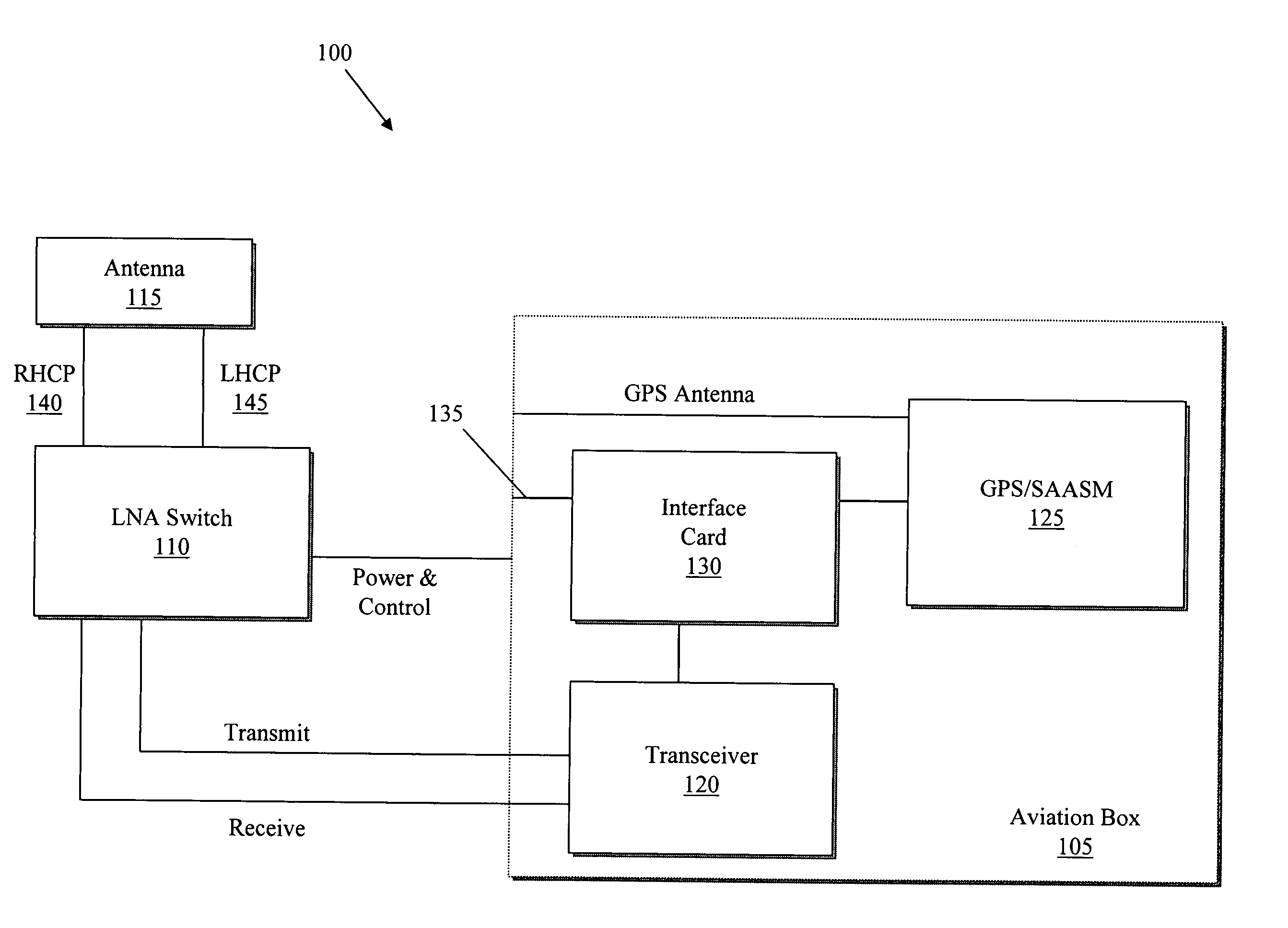
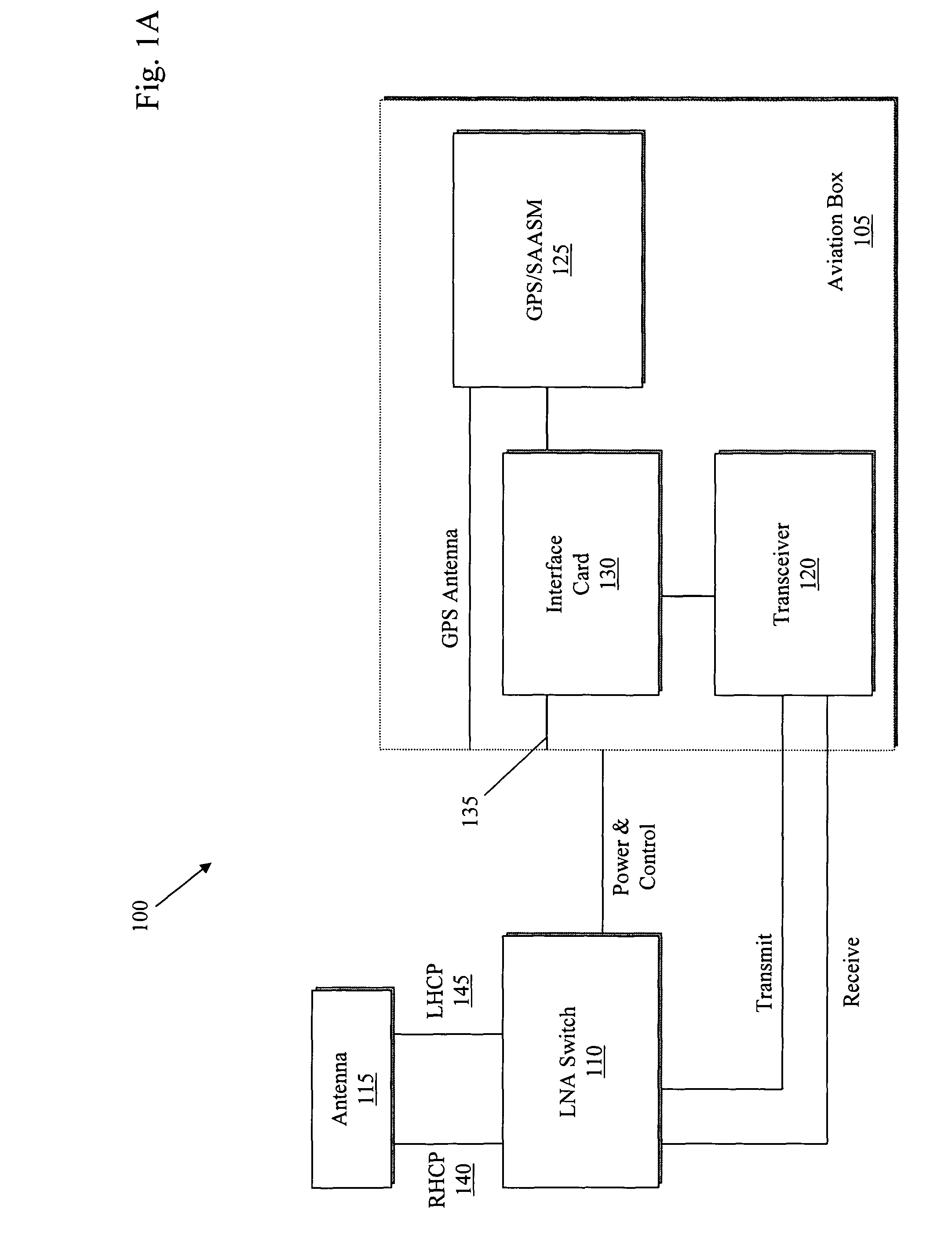
[0022]The system provides satellite communications such as two-way messaging and position reporting for fixed and rotary wing aircrafts, where traditional methods of communications are not otherwise practical. The system keeps remote users connected to other remote users and to control stations and provides location visibility. This functionality solves two specific problems for military applications: it reduces the number of casualties by having a means of receiving / sending critical information quickly and securely, and maintains better control and visibility of geographically dispersed vehicles, soldiers, and other assets.

[0023]The in-flight transceiver system is developed specifically to meet BlueForce Tracking Aviation's requirements. Specifically, the system operates under temperature extremes and Electromagnetic Interference protection is provided. As such, the system meets the Aviation Applied Technology Directorate's (AATD) test for airworthiness, MIL-STD-810—environmental e...


PUM


Abstract

Military systems in particular face two specific problems: field casualties typically increase as unit visibility decreases and it is often difficult for ground stations and / or headquarters to maintain control and visibility of geographically dispersed assets. The system provides satellite communications such as two-way messaging, Voice over Packet, and global positioning information and reporting for fixed and rotary wing aircrafts where traditional methods of communications are not otherwise practical. The system provides communications between remote users and other remote users as well as between remote users and control stations. In some embodiments there is an in-flight transceiver system that includes an antenna, an aviation box, and a switch. The aviation box conforms to a one-half, ½ short Air Transport Rack (ATR) form factor and includes a transceiver, an interface card, and a global positioning system (GPS) unit. The switch is located between the aviation box and the antenna for controlling a data signal between the antenna and the transceiver of the aviation box.

Description

CROSS-REFERENCE TO RELATED APPLICATION[0001]This application claims priority to and the benefit of, and incorporates herein by reference, in its entirety, provisional U.S. patent application Ser. No. 60 / 733,268, filed Nov. 2, 2005.FIELD OF THE INVENTION[0002]The present invention relates generally to transceiver systems and specifically to in-flight transceiver and locator systems.BACKGROUND[0003]Current attempts at in-flight transceiver and locator systems are bulky and do not provide real-time data updates. Specifically, systems are not typically small enough to fit inside an aircraft's cockpit and the data exchanged between transceiver, satellite, ground units and / or headquarters experience delays of ten seconds or more. In a battlefield scenario, even mere seconds are crucial. Additionally, due to space constraints, the housing that encases components of an in-flight transceiver and locator system typically provides limited connectivity to users or engineers and mechanics attemp...

Claims


Application Information

Patent Timeline
Patent Type & Authority Patents(United States)
IPC IPC(8): H04W4/00G01S1/00H04B7/185
CPCG01S5/0027G01S19/18H04B1/3805
Inventor MEYERS, THOMAS DANIELTHORNE, CHRISTOPHER RICHARDHULCHER, PHILIPP LYNN
Owner COMTECH MOBILE DATACOM CORP
Why Eureka
Try Eureka