
Steam boiler

a steam boiler and corrosive technology, applied in the direction of machines/engines, speed sensing governors, lighting and heating apparatus, etc., can solve the problems of unintended losses, water must be added to the boiler, and loss of water due to loss

Inactive Publication Date: 2010-11-02
ECR INT
View PDF14 Cites 7 Cited by
  • Summary
  • Abstract
  • Description
  • Claims
  • Application Information

AI Technical Summary

Benefits of technology

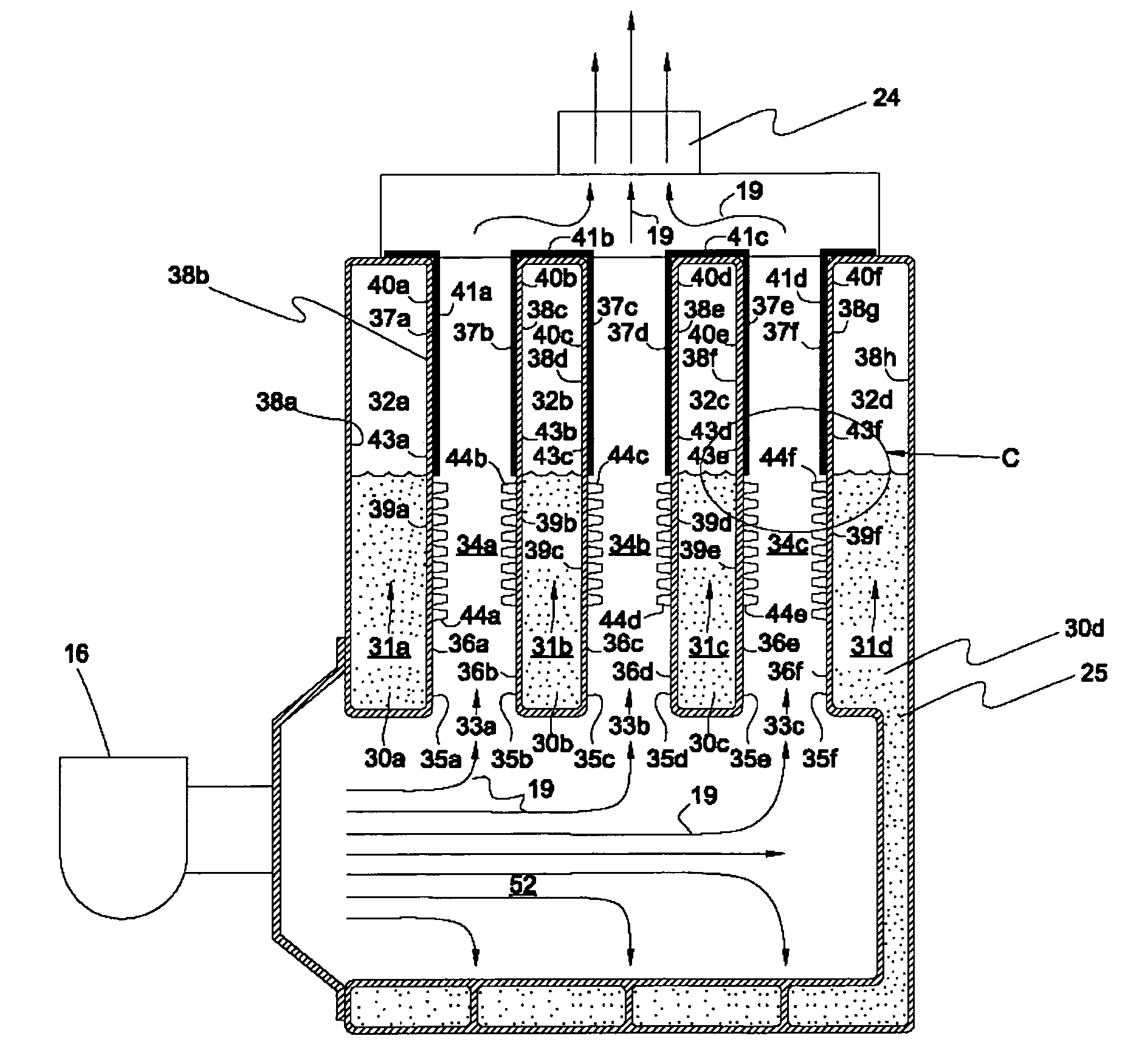
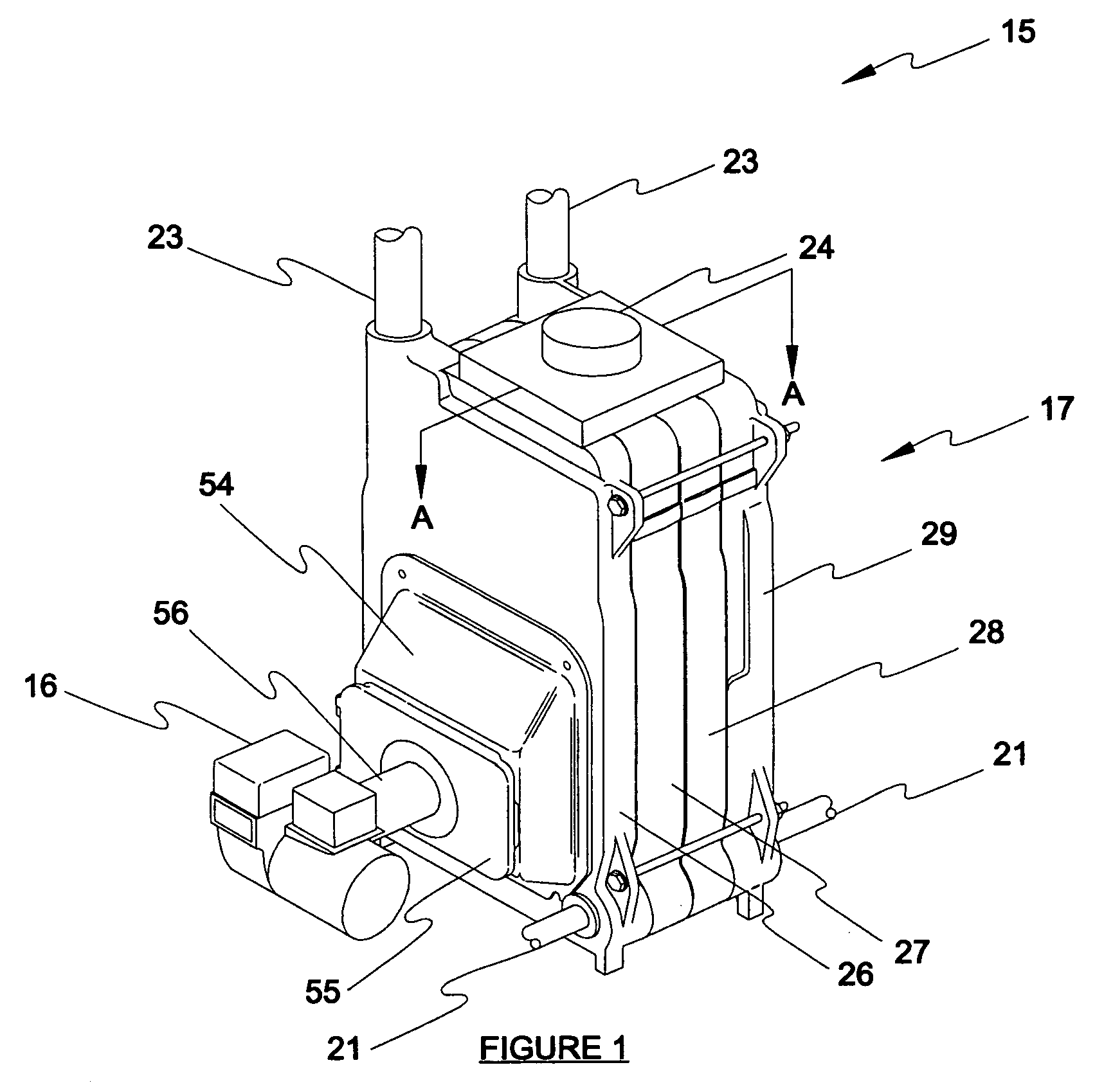
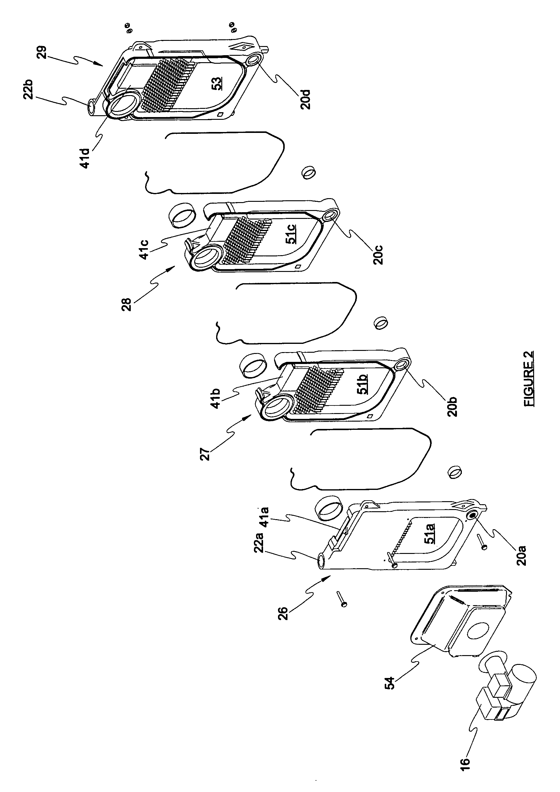
"The present invention provides an improved steam boiler that is resistant to corrosion. The boiler includes a fuel burning device, a combustion chamber, a water inlet, a steam outlet, a flue passage, a heat exchange element, and a heat shield. The heat shield covers at least some of the surface area of the gas-side second portion. The heat exchange element has a gas-side surface that absorbs heat from the heat transfer space and a water-side surface that radiates heat. The water-side surface has a first portion adjacent to the water space and a second portion adjacent to the steam space. The gas-side first portion has a surface area and the gas-side second portion has a surface area. The heat shield may cover all or some of the surface area of the gas-side second portion. The heat shield may be a metal plate or an insulation layer. The heat exchange element has a ratio between the surface area of the gas-side first portion and the surface area of the water-side first portion that is greater than one and a ratio between the surface area of the gas-side second portion and the surface area of the water-side second portion that is less than the ratio between the surface area of the gas-side first portion and the surface area of the water-side first portion. The technical effect of the invention is to provide a steam boiler that is resistant to corrosion."

Problems solved by technology

Occasionally, water must be added to the boiler because of intended and unintended losses.
Intended losses may include loss e of water to flush or blow down the mechanical float water level control, loss e of water to flush or blow down sediment from the bottom of the boiler, and loss e of water due to the escape of steam through the vent valves.
Unintended losses may include leaking radiator vents and leaking in the pipe system.
However, prior art boilers tend to corrode or degrade over time and with use.

Method used


Image

  • Steam boiler
  • Steam boiler
  • Steam boiler

Examples


Embodiment Construction

[0018]At the outset, it should be clearly understood that like reference numerals are intended to identify the same structural elements, portions or surfaces consistently throughout the several drawing figures, as such elements, portions or surfaces may be further described or explained by the entire written specification, of which this detailed description is an integral part. Unless otherwise indicated, the drawings are intended to be read (e.g., cross-hatching, arrangement of parts, proportion, degree, etc.) together with the specification, and are to be considered a portion of the entire written description of this invention. As used in the following description, the terms “horizontal”, “vertical”, “left”, “right”, “up” and “down”, as well as adjectival and adverbial derivatives thereof (e.g., “horizontally”, “rightwardly”, “upwardly”, etc.), simply refer to the orientation of the illustrated structure as the particular drawing figure faces the reader. Similarly, the terms “inwa...


PUM


Abstract

A steam boiler (15) comprising a fuel burning device (16) disposed in a combustion chamber and adapted to burn a fuel to form combustion gases (19), a passage (30) extending between a water inlet (20) and a steam outlet (23), the passage having a water space (31) and a steam space (32), a flue passage (33) extending between the combustion chamber and a flue outlet (24) and having a gas heat transfer space (34), a heat exchange element (43) between the gas heat transfer space and the water and steam spaces, the heat exchange element having a gas-side surface (35) that absorbs heat from the combustion gases and an opposed water-side surface (38) that radiates heat, the water-side surface having a first portion (39) adjacent to the water space and a second portion (40) adjacent to the steam space, the gas-side surface having a first portion (36) opposite the water-side first portion and a second portion (37) opposite the water-side second portion, the water-side first portion having a surface area and the water side second portion having a surface area, the gas-side first portion having a surface area and the gas-side second portion having a surface area, and a heat shield (41, 42, 45, 48) covering at least some of the surface area of the gas-side second portion. The surface area of the gas-side first portion may be greater than the surface area of the water-side first portion and the surface area of the gas-side second portion may be less than or approximately equal to the surface area of the water-side second portion.

Description

TECHNICAL FIELD[0001]The present invention relates generally to the field of steam boilers, and more particularly to a corrosive resistant steam boiler.BACKGROUND ART[0002]Steam boilers are well-known in the prior art and have been used in residential heating applications for years. Most steam boiler systems known in the prior art include a boiler connected to radiators by a pipe system. The pipe system allows steam to rise into the radiators, pushing the ambient air out of the radiators, until a steam vent valve on the radiator closes due to the temperature rise. The steam then condenses against the inside surface of the radiator and trickles back to the boiler by gravity through the same pipe system. Thus, most steam heating systems are open systems that are filled with air during the off cycle. The air is forced out the system when the boiler is steaming. At the end of a call for heat, the steam field collapses and draws air back into the system.[0003]Generally, residential steam...

Claims


Application Information

Patent Timeline
Patent Type & Authority Patents(United States)
IPC IPC(8): F28F19/00F22B1/26
CPCF22B9/10
Inventor CHRISTIE, DAVID M.
Owner ECR INT
Learn More