Wheel spindle device for grinding machine

a technology of grinding machine and spindle, which is applied in the direction of gear teeth, manufacturing tools, gear teeth, etc., can solve the problems of workpiece displacement away from the grinding wheel, deterioration of machining accuracy and machining efficiency, and change in grinding resistance, so as to enhance the machining accuracy of workpieces and reduce the fluctuation of grinding resistance

Inactive Publication Date: 2010-11-02
TOYODA VAN MOPPES +1
View PDF19 Cites 4 Cited by
  • Summary
  • Abstract
  • Description
  • Claims
  • Application Information

AI Technical Summary

Benefits of technology

[0010]It is therefore a primary object of the present invention to provide an improved assembling structure that a plurality of grinding wheels each with inclined grooves formed on a grinding surface thereof are mounted on a wheel spindle and that is capable of enhancing production efficiency without increasing the fluctuations in the grinding resistances between a workpiece and respective grinding wheels and also capable of enhancing the machining accuracy.
[0012]Where inclined grooves are formed on a grinding surface of a grinding wheel, a grinding resistance between the grinding wheel and a workpiece ground therewith fluctuates at respective time points with a variation in the number of the inclined grooves passing across a grinding point as well as in a tiny or slight change in shape of the inclined grooves. With the aforementioned construction of the invention, however, since the inclined grooves formed on one grinding wheel and those formed on another grinding wheel are shifted through different angular distances relative to the reference position defined on the core member of each grinding wheel not to coincide between the grinding wheels, the fluctuations in the grinding resistances on the respective grinding wheels can be mitigated not to grow as a combined or synergy effect through synchronization between the grinding wheels. As a consequence, the fluctuation in the grinding resistance is reduced in the direction normal to the grinding surface, so that it can be realized to enhance the machining accuracy of the workpiece.

Problems solved by technology

Therefore, it is necessary to prevent the machining accuracy and the machining efficiency from being deteriorated as a result that the dynamic pressure causes the workpiece to be displaced away from the grinding wheel.
This undesirably causes the area on the grinding surface (i.e., the area of abrasive grains of the grinding wheel which contacts the workpiece) to vary in dependence on the positions of the inclined grooves or the rotational angle of the grinding wheel, whereby change occurs in the grinding resistance.
Further, it may be the case that it is difficult as practical matter to make the inclined grooves uniform in width.
The lack of uniformity in the inclined grooves formed on the grinding surface likewise causes the grinding resistance to fluctuate.
This may undesirably results in chattering as the case may be, and may give rise to a drawback that the machining accuracy of the workpiece is deteriorated.

Method used


Image

  • Wheel spindle device for grinding machine
  • Wheel spindle device for grinding machine
  • Wheel spindle device for grinding machine

Examples


first embodiment

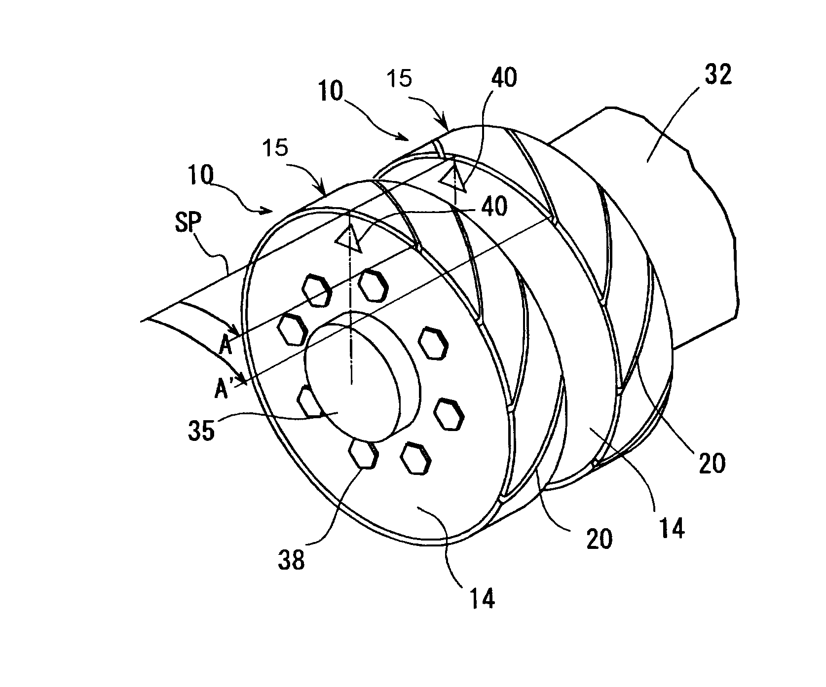
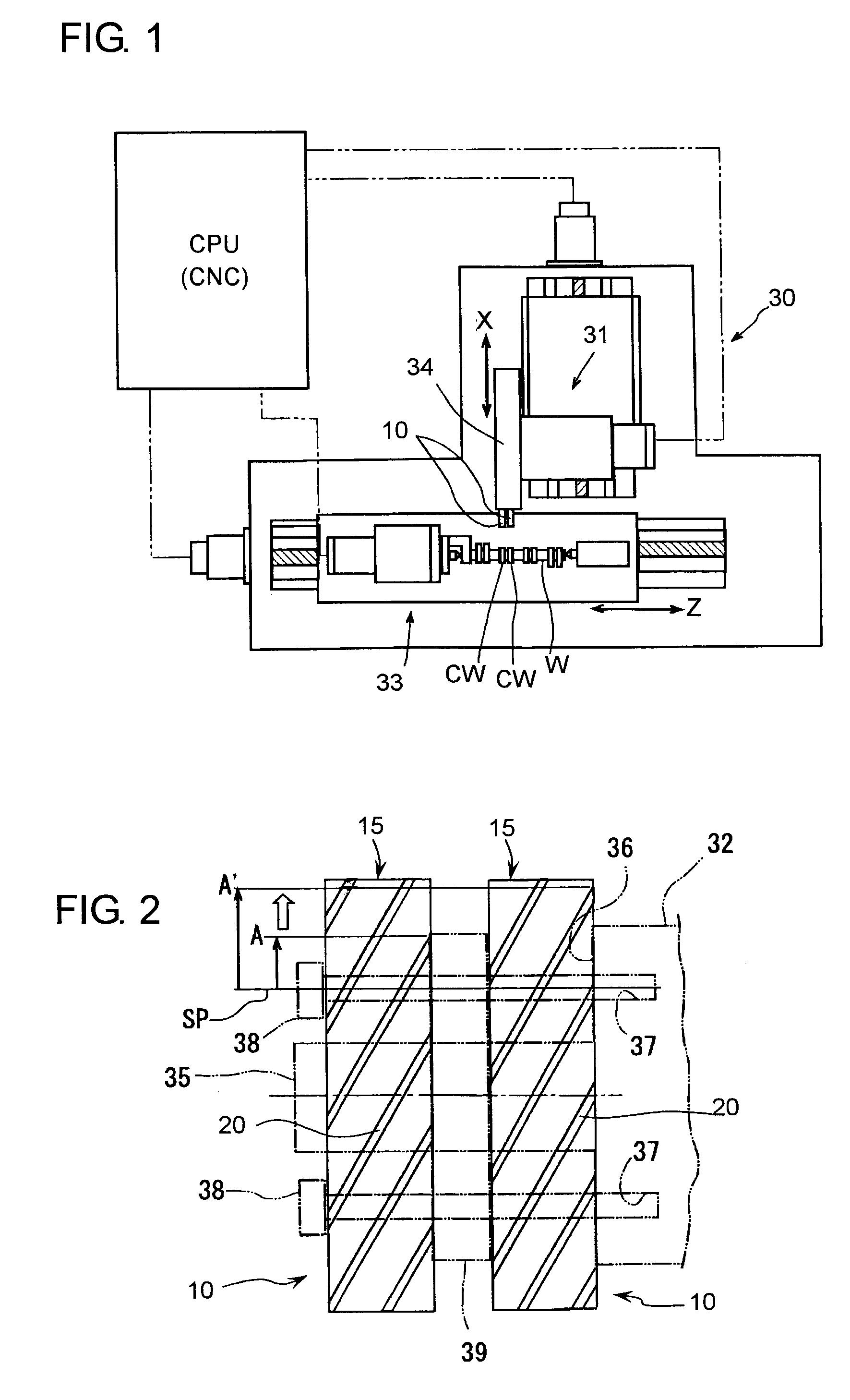
[0025]Hereafter, a wheel spindle device for a grinding machine in a first embodiment according to the present invention will be described with reference to the accompanying drawings. Referring now to FIG. 1, there is shown a cylindrical grinding machine 30, wherein a camshaft W of a so-called “twin-cam type” as workpiece is rotatably supported by a workpiece support device 33 which comprises a work head and a foot stock (both not numbered). Two grinding wheels 10 referred to later in detail which are assembled to a wheel spindle 32 (FIG. 2) of a wheel head 31 are covered with a wheel cover device 34, to which a coolant nozzle (not shown) is attached. Coolant is supplied from the coolant nozzle toward a grinding point between the grinding wheel 10 and the workpiece W. When the wheel head 31 is advanced, grinding surfaces 15 (FIG. 2) which are formed as circumferential surfaces of abrasive grain layers 12 (FIG. 5) of the two grinding wheels 10 are brought into contact respectively wit...


PUM

PropertyMeasurementUnit
thicknessaaaaaaaaaa
depthaaaaaaaaaa
outer diameteraaaaaaaaaa

Abstract

In a wheel spindle device wherein a plurality of grinding wheels are attached in a juxtaposed relation to a wheel spindle rotatably carried on a wheel head of a grinding machine, a reference position for specifying a position in the circumferential direction of the grinding wheel is provided on a core member of each of the grinding wheels, and a plurality of inclined grooves at predetermined angular intervals are formed on a grinding surface of each grinding wheel to be inclined relative to the circumferential direction of each grinding wheel. In order that the fluctuations in the dynamic pressure and the grinding resistance between respective grinding wheels and workpiece portions ground therewith do not grow as a combined or synergy effect, the inclined grooves on each grinding wheel are shifted in angular phase from those on another grinding wheel, so that grinding efficiency and accuracy can be enhanced.

Description

INCORPORATION BY REFERENCE[0001]This application is based on and claims priority under 35 U.S.C. 119 with respect to Japanese patent application No. 2007-151981 filed on Jun. 7, 2007, the entire content of which is incorporated herein by reference.BACKGROUND OF THE INVENTION[0002]1. Field of the Invention[0003]The present invention relates to a wheel spindle device for mounting a plurality of grinding wheels with inclined grooves formed on grinding surfaces thereof, on a wheel spindle of a grinding machine.[0004]2. Discussion of the Related Art[0005]In Japanese unexamined, published patent application No. 2000-354969, there is described a grooved grinding wheel, wherein an abrasive grain layer including super abrasive grains such as, for example, diamond or cubic boron nitride (CBN) is formed on a circumferential surface of a disc-like core member drivingly rotated about an axis. Oblique or inclined grooves each having a predetermined width and a predetermined depth are formed on a ...

Claims


Application Information

Patent Timeline
Patent Type & Authority Patents(United States)
IPC IPC(8): B24B49/00B24B45/00B24D5/00
CPCB24B19/12B24D5/10
Inventor INAGAKI, TOMOHIROIMAI, TOMOYASUMOROTO, TAKAYUKISOMA, SHINJI
Owner TOYODA VAN MOPPES
Why Eureka
Try Eureka