Chest tube drainage system

a drainage system and chest tube technology, applied in the field of chest tube drainage system, can solve the problems of kinking of the tubing, insufficient air exchange for patients, and most difficult monitoring, and achieve the effect of facilitating the maintenance of a continuous flow of air

Active Publication Date: 2010-11-02
3M INNOVATIVE PROPERTIES CO
View PDF239 Cites 21 Cited by
  • Summary
  • Abstract
  • Description
  • Claims
  • Application Information

AI Technical Summary

Benefits of technology

[0014]A number of chest tube terminal structures for insertion into the pleural space of a patient are disclosed in the system of the present invention, including multi-lumen structures having both high-airflow and low-airflow lumens. Fenestrations in the form of small slits or the like in the tubular walls are variously positioned between the lumens and between the interior and exterior spaces defined by the lumens, in order to collect coagulated components of the extracted fluids and facilitate the maintenance of a continuous flow of air.

Problems solved by technology

However, if a considerable amount of fluid or blood that cannot be absorbed by the body itself is present, chest tubes and a drainage system will typically be required.
When there is an excess amount of fluid or air in the pleural space, simply having an open airway will not typically result in sufficient air exchange for the patient due to the likely presence of a partial or complete lung collapse.
Each of these systems operated under the basic principles of gravity, positive pressure, and suction, with the one bottle system being the simplest, yet most difficult to monitor.
Several difficulties arise with systems heretofore described in the art, including the kinking of the tubing, the formation of clots and blockages, problems with the suction, and problems with dependent loops (air and fluid) in the tubing.
Additionally, the classic bottle systems, even those that involve an integrated three chamber structure, are typically quite bulky and do not allow easy transportation or ambulation of the patient.
Although some integrated systems have been developed that are directed to being lightweight, portable, non-breakable, and disposable, many problems with the collection tubing still exist.
Additionally, these types of devices typically must be connected to large pump systems or stationary vacuum sources which decrease or altogether eliminate their portability.
A problem almost universally encountered within the prior art is the inadequate drainage of the intrapleural space due to clots or gelatinous inflammatory material and the resultant plugging or kinking of the tube.
Another frequent problem in the prior art is the disposal of the biohazardous fluids from the drainage collection chambers.

Method used


Image

  • Chest tube drainage system
  • Chest tube drainage system
  • Chest tube drainage system

Examples


first embodiment

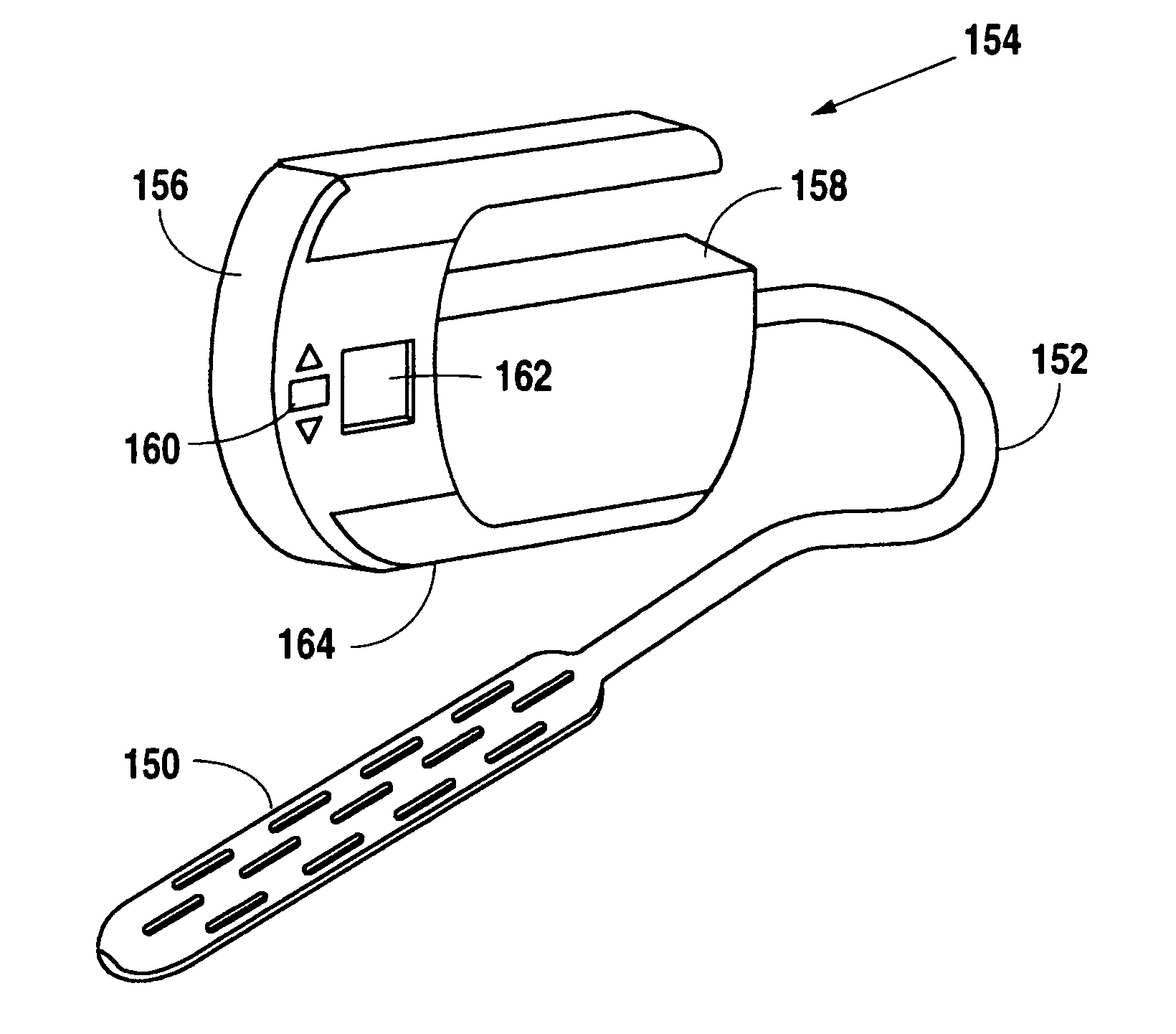
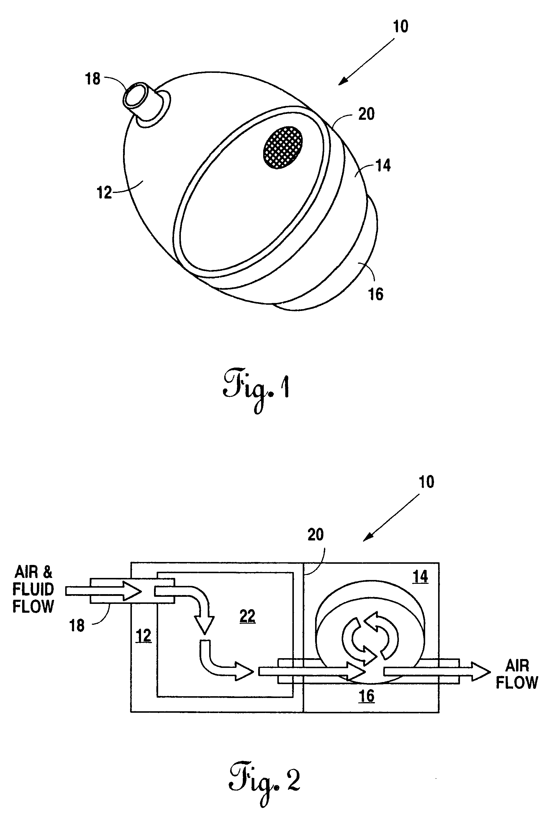
[0041]the suction device of the present invention described above with respect to FIGS. 1 & 2 may be constructed small enough and of readily available materials and components as to allow the unit to be completely disposable (i.e. a single patient, single use device). The desiccant chamber section (12 in FIG. 1) may be replaced as needed for a particular patient while the entire device might be disposed of after use is completed for the particular patient.

[0042]The first embodiment of the suction device of the present invention described above may also find application in other medical situations not involving chest tube placement and drainage. The low vacuum device could, for example, be utilized as a very small wound pump to provide a sub-atmospheric pressure on a healing wound as has become beneficially evident in the wound treatment field. The airflow volume required for a chest tube pump would generally be higher, and the volume required for a wound pump generally lower. Variat...

second embodiment

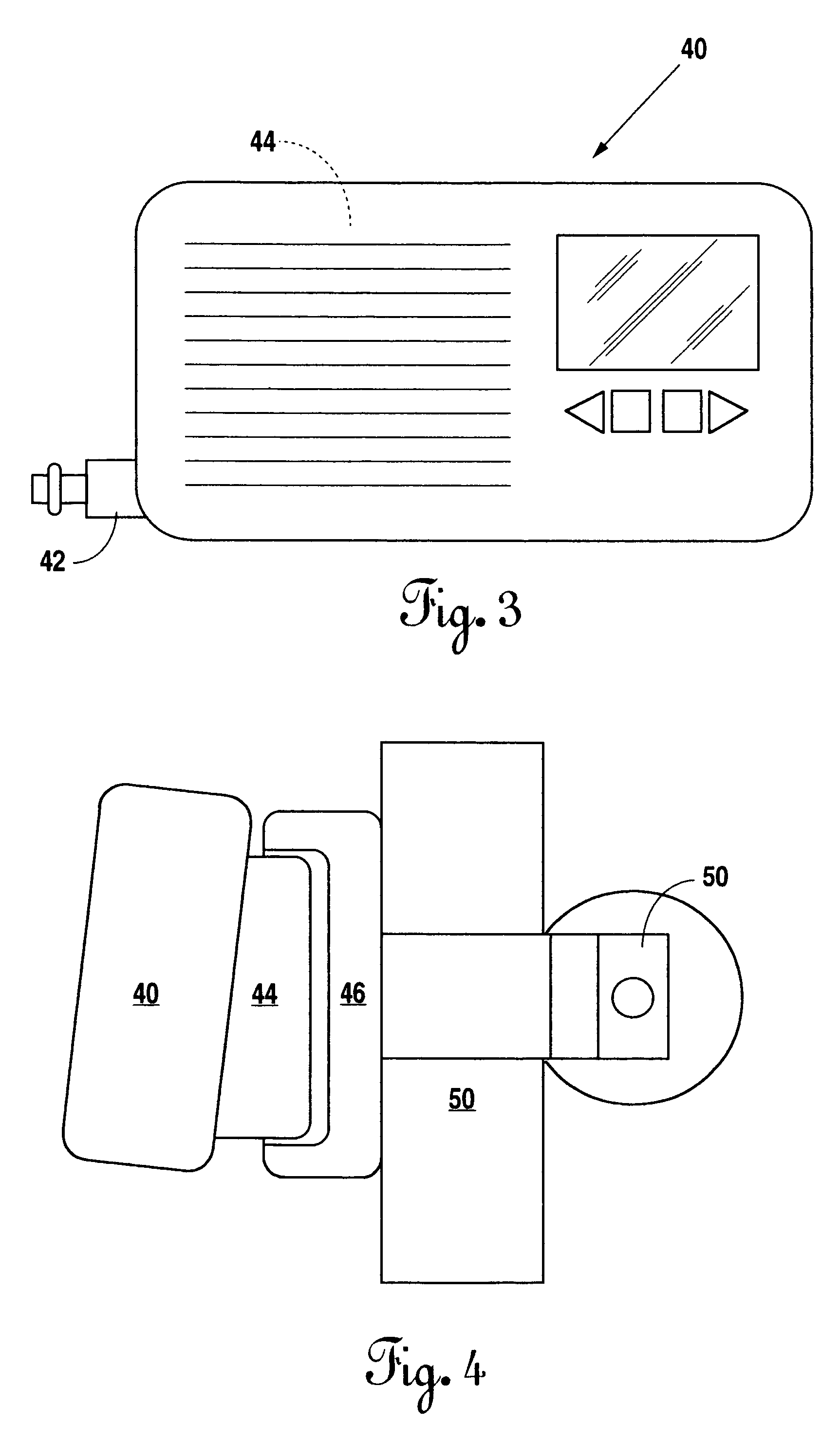
[0043]the suction device of the present invention described above with respect to FIGS. 3 & 4 would be constructed in a manner similar to the device described in the referenced U.S. Pat. No. 6,648,862. In so far as the device described in this referenced U.S. Patent is primarily directed to the wound healing arts, the structure of a similar device appropriate for use with chest drainage would require modifications that would increase the airflow volume through the device and the capacity of the desiccant chamber. The desiccant material (contained within the desiccant pouch) and the chamber within which it is positioned, would be separately disposable apart from the motor / pump section and the power section of the device.

[0044]The device of this second embodiment would also lend itself to the use of more complex automated decision algorithms that may serve to control the airflow rates and respond to changes in pressure within the system. This increased electronic control complexity al...


PUM


Abstract

A system for draining the chest cavity of a patient subjected to a traumatic chest injury and / or to surgery within the chest. The system includes a small, portable suction device and a chest tube with an improved terminal structure. A number of embodiments of the suction device are disclosed; the first (with two variations) a small, completely disposable, bottle-shaped assembly comprising a motor / pump section, a power section, and a desiccant filled chamber, the second (also with two variations) a small box shaped assembly with a disposable desiccant pouch and a power supply that mounts to a battery charger positioned on an IV pole. A number of chest tube terminus structures are disclosed, including multi-lumen structures having high-airflow and low-airflow lumens as well as “dead” and “live” lumens. Fenestrations are variously positioned between and through the lumens in order to collect coagulated components of the extracted fluids and prevent them from clogging the primary flow tube and restricting or preventing continuous airflow.

Description

[0001]This application is based upon and claims priority from U.S. Provisional application Ser. No. 60 / 600,229, filed Aug. 10, 2004, which is incorporated herein by reference.BACKGROUND OF THE INVENTION[0002]1. Field of the Invention[0003]The present invention relates generally to medical and surgical devices and systems that serve to remove air and fluids from the body of a patient after injury or during and after surgery. The present invention relates more specifically to a system for use in association with the removal of air and fluids from the chest cavity of a patient during surgery or as a manner of treatment for a chest injury.[0004]2. Background Information[0005]The human chest cavity is lined with membranes referred to as the parietal pleura and the visceral pleura. The parietal pleura line the chest cavity itself, while the viscera pleura are the membranes that line the lungs. The space between the two membranes is called the intrapleural space (or sometimes simply “the p...

Claims


Application Information

Patent Timeline
Patent Type & Authority Patents(United States)
IPC IPC(8): A61F13/00A61M1/00
CPCA61M1/0023A61M1/0096A61M2210/101A61M1/882A61M1/74
Inventor WATSON, JR., RICHARD L.
Owner 3M INNOVATIVE PROPERTIES CO
Why Eureka
Try Eureka