Guide for a medical device

a medical device and guide technology, applied in the direction of mechanical control devices, manual control devices with multiple controlling members, manual control with single controlled members, etc., can solve the problems of inability to position the distal tip of a puncturing device and considerable disadvantages

Active Publication Date: 2010-11-02
APRIOMED
View PDF17 Cites 61 Cited by
  • Summary
  • Abstract
  • Description
  • Claims
  • Application Information

AI Technical Summary

Benefits of technology

[0012]In one embodiment, the puncturing guide according to the present invention comprises a base plate having a flat bottom and being provided with three flat legs for attachment on a patient's skin, a tubular needle guide, in which a puncturing needle is to be inserted, and a retainer, which secures the needle guide to the base plate by means of a bayonet coupling. In the center of the base plate, a first semi-sphere is provided, and a bore extends from the top of the semi-sphere to the bottom of the base plate. The outer radius of this first semi-sphere is the same as the inner radius of a segment of a second semi-sphere being provided on the shaft of the needle guide. During an angle adjusting operation, the segment of the second semi-sphere slides on the first semi-sphere, with the tubular needle guide pointing at an object beneath the base plate through the bore in the first semi-sphere. For this puncturing guide, the centre of the first semi-sphere constitutes the rotational centre of the needle guide, and it is therefore possible to position the tip of a puncturing needle at a puncturing point located at a patient's skin and then set the entrance angle of the puncturing needle without changing its entrance point.

Problems solved by technology

This means that it is not possible to position the distal tip of a puncturing device at the puncturing point in a first operation and then, in a second operation, set the entrance angle of the puncturing device without changing the entrance point of the puncturing device.
In some applications this is a considerable disadvantage, as will be described below.

Method used


Image

  • Guide for a medical device
  • Guide for a medical device
  • Guide for a medical device

Examples


first embodiment

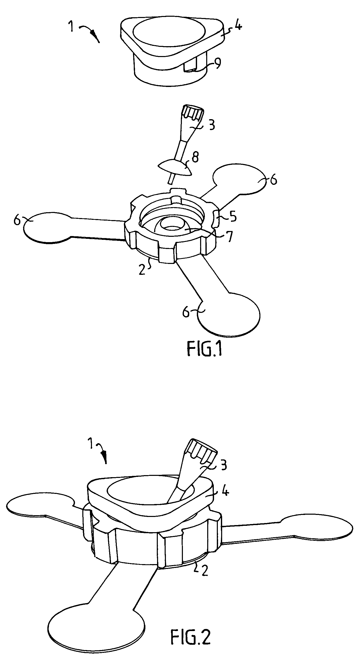
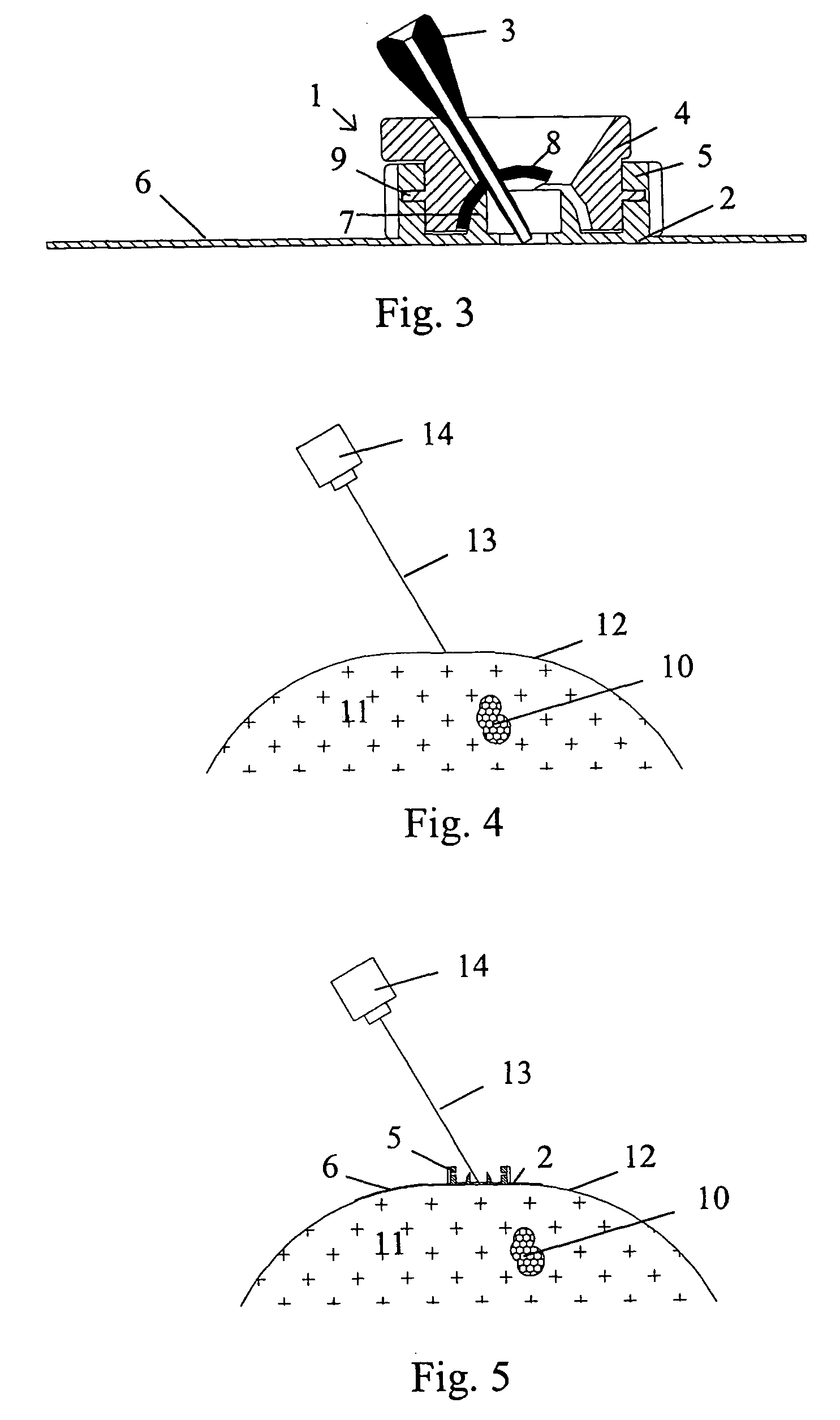
[0024]a puncturing guide according to the present invention will be described in conjunction with FIG. 1 to FIG. 3. In FIG. 1 is shown a puncturing guide 1 in a disassembled state. The puncturing guide 1 comprises basically a base plate 2, a tubular needle guide 3 and a retainer 4. The base plate 2, in turn, comprises a central, ring-shaped member 5 and flat legs 6, e.g. three, the undersides of which preferably are provided with a suitable adhesive for attachment to a patient's skin. On the central part of the ring-shaped member 5, a first sliding surface in the form of a first segment 7 of a first semi-sphere is provided. In the center of this first semi-sphere, a bore is formed, which extends from the top of the semi-sphere to bottom of the base plate 2. The outer radius of this first semi-sphere is the same as the inner radius of a second sliding surface in the form of a second segment 8 of second semi-sphere, which is provided on the shaft of the needle guide 3. In this preferr...

second embodiment

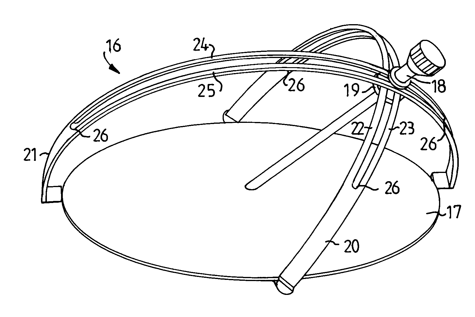
[0034]The possibility to divide the angular adjustment of the puncturing needle and its positioning at the puncturing point into two separate, independent steps is clearly dependent on the special feature of the present puncturing guide, i.e. that the needle guide is movable around the center point of the first semi-sphere, which center point in use is located at the puncturing point. This feature can be achieved with other arrangements. FIG. 10 and FIG. 11 illustrate a puncturing guide 16 in a first and second orientation, respectively. The puncturing guide 16 comprises basically a flat base plate 17, a tubular needle guide 18, a ring-shaped retainer 19, a first segment 20 of a first semi-sphere, and a second segment 21 of a second semi-sphere.

[0035]The segments have the shapes of two semi-circular equally sized bows pivotally attached to the base plate 17 at positions separated by 90°, and that a slit is provided in each bow, wherein the needle guide 18 is adapted to be arranged i...


PUM


Abstract

The invention provides a puncturing guide (1, 16) for guiding a puncturing needle into a target site within the body of a patient. The puncturing guide (1, 16) comprises a base plate (2, 17), a needle guide (3, 18), a retainer (4, 19) for securing the needle guide (3, 18) to the base plate (2, 17), a first segment (7, 20) of a first semi-sphere, a second segment (8, 21) of a second semi-sphere, and a needle guide (3, 18) attached to the second segment (8, 21). During a positioning operation, the second segment (8, 21) slides on the first segment (7, 20), so that the needle guide (3, 18) is movable around the center of the first semi-sphere, which is in level with the underside of the base plate (2, 17), thereby providing the possibility to position the tip of a puncturing needle at a puncturing point on the patient's skin and then, in a separate operation, set the entrance angle of the puncturing needle without changing its entrance point.

Description

FIELD OF THE INVENTION[0001]The present invention relates generally to a guide for guiding a medical instrument to a target site within a patient's body, and more particularly to a puncturing guide for guiding a puncturing instrument, e.g. a biopsy instrument, to a target site, the position of which has been determined by means of computerized tomography (CT), magnetic resonance imaging (MRI), ultra sound or the like.BACKGROUND OF THE INVENTION[0002]CT is used to provide doctors with a cross-sectional picture of a patient's internal organs and tissues; and if a puncturing operation is to be performed, the CT-scanner provides the doctor with image data from which the doctor determines the puncturing position, the direction and the depth for a puncturing device so as to reach the target site. In some cases, the puncturing device is manipulated without employing any device for guiding the puncturing needle, but often some kind of guiding device is used.[0003]A variety of guides employe...

Claims


Application Information

Patent Timeline
Patent Type & Authority Patents(United States)
IPC IPC(8): A61B19/00A61B17/34
CPCA61B17/3403Y10T74/20305A61B19/201A61B90/11
Inventor MAGNUSSON, ANDERSEGNELOV, PER
Owner APRIOMED
Why Eureka
Try Eureka