
Device for balancing cell voltage for a secondary battery

a secondary battery and cell voltage technology, applied in the field of cell voltage balancers, can solve the problems of high complexity, high cost, and the inability to accurately suppress cell voltage variations, and achieve the effect of highly accurate suppression of cell voltage variations

Active Publication Date: 2010-11-02
GS YUASA INT LTD
View PDF8 Cites 7 Cited by
  • Summary
  • Abstract
  • Description
  • Claims
  • Application Information

AI Technical Summary

Benefits of technology

This approach accurately balances cell voltages while avoiding upsizing and complexity, reducing heat and current demands, and enabling reliable operation in applications requiring high precision, such as aircraft systems, by maintaining a float charge state and using standard components like MOSFET transistors or mechanical relays.

Problems solved by technology

However, in the case of using the above technique (1), there has been a problem in that the cell voltage exceeds the charge target voltage even though the switch is switched from the open state to the closed state.
Further, also in the case of using the above technique (2), there has been a problem in that the same condition as the above takes place if a voltage is close to the charge target voltage when the variations are large.
When the cell voltage exceeds the charge target voltage, a process of re-discharging that cell alone needs to be performed, which is highly complicated.
Under such circumstances, there has been a problem of upsizing the cell voltage balancer.
Further, there has also been a problem of having to release heat generated by the resistor.
Moreover, in the case of the above technique (3), there has been a problem of increasing costs for development and production of the balancer for securing high reliability in terms of both hardware and software.
Furthermore, there has also been a problem of not being able to use the above technique (3) in the first place depending upon applications since the use of a complicated component such as a microprocessor is restricted in applications where extremely high reliability is required (e.g. application for aircraft).

Method used


Image

  • Device for balancing cell voltage for a secondary battery
  • Device for balancing cell voltage for a secondary battery
  • Device for balancing cell voltage for a secondary battery

Examples


Embodiment Construction

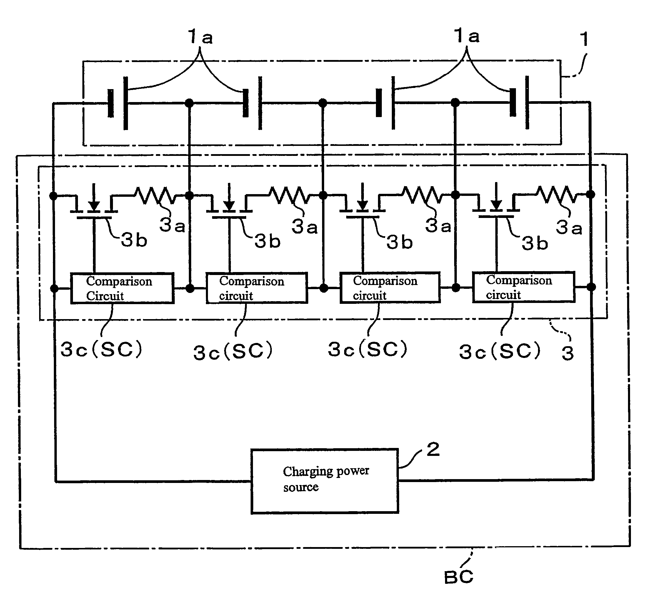
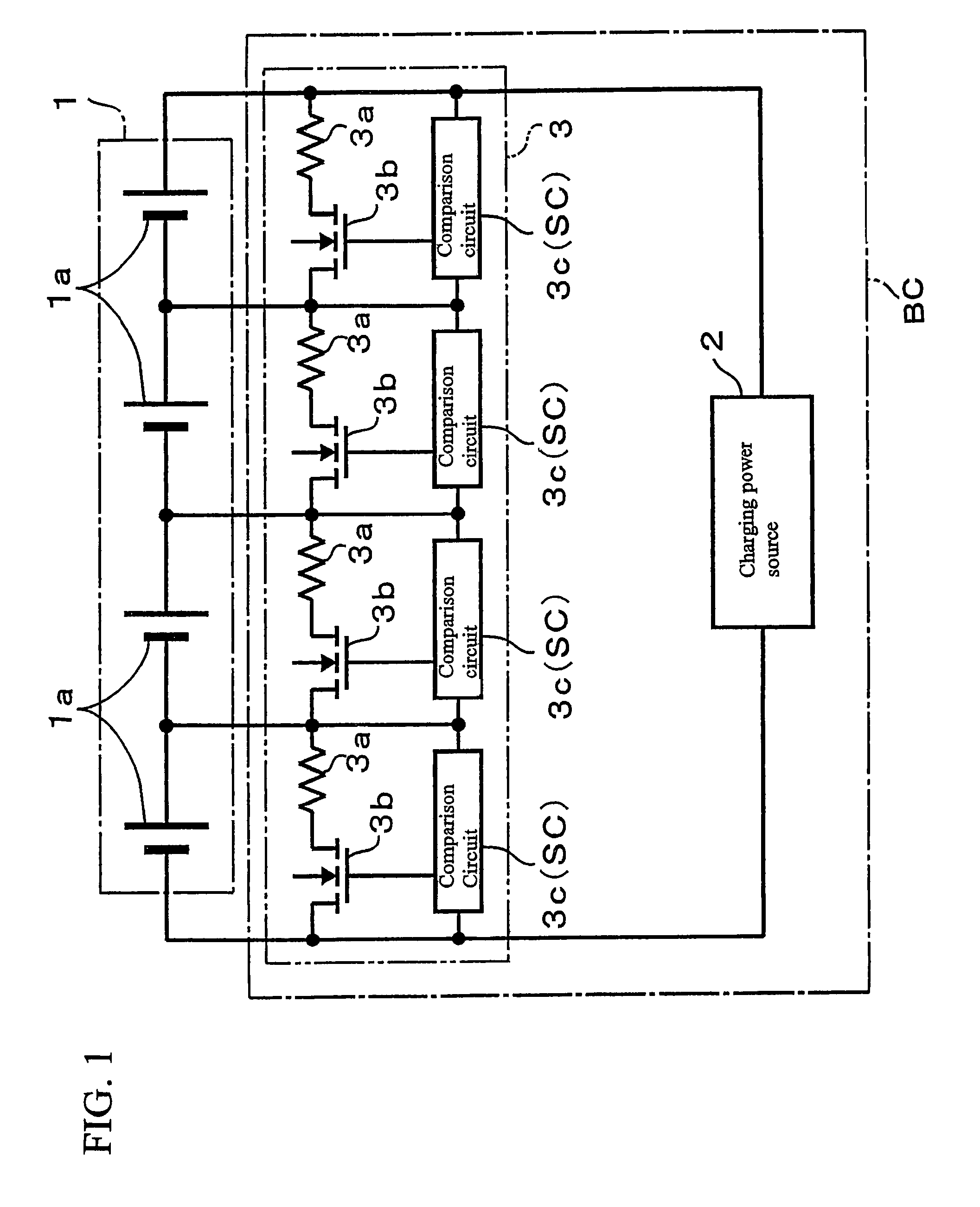
[0038]Embodiments of a cell voltage balancer of the present invention are described based upon drawings. Here described is a case where the cell voltage balancer is provided as part of a charger of a lithium ion battery as an example of a secondary battery.

[0039]In the present embodiment, an object to be charged is a battery pack as in FIG. 1. The battery pack is configured by serially connecting cells 1a. Since the cell 1a is a lithium ion battery, the battery pack as a whole is also a lithium ion battery. A charger BC for charging this lithium ion battery 1 includes a charging power source 2 for supplying the lithium ion battery 1 with a charging current and a cell voltage balancer 3.

[0040]Here assumed is a case where the charger BC of the present embodiment is installed on an aircraft along with the lithium ion battery 1. Therefore, the number of cells 1a configuring the lithium ion battery 1 is in reality larger than the number shown in FIG. 1, but a case where the number of cel...


PUM

PropertyMeasurementUnit
internal resistanceaaaaaaaaaa
resistanceaaaaaaaaaa

Abstract

The present invention is a method for balancing voltages of a serially connected plurality of cells in a battery pack provided with the plurality of cells. In this method, the voltages are balanced by: connecting a pair of a resistor and a switch, which are serially connected with each other, in a parallel relationship to one of the plurality of cells; switching the switch from an open state to a closed state when a voltage of the one cell increases to a prescribed balance operation starting voltage; and maintaining a state where the cell is charged by a voltage of the same magnitude as a voltage that is applied to both ends of the pair after switching of the switch to the closed state.

Description

BACKGROUND OF THE INVENTION[0001]1. Field of the Invention[0002]The present invention relates to a cell voltage balancer with the aim of equalizing voltages of a plurality of cells configuring a battery pack.[0003]2. Description of the Related Art[0004]A plurality of cells (here, a cell means a chargeable secondary battery) are serially connected to configure a battery pack. Even when such a battery pack is charged, the cells therein may vary in voltage. This is caused by a difference in degree of progress of charge among the cells even when the battery pack is charged at a constant current due to the presence of variations in value of internal resistance and the like among the cells. A device for eliminating the variations in cell voltage as thus described is generally called a “cell voltage balancer”.[0005]A circuit is loaded on the cell voltage balancer. A configuration of the circuit is under studies from a variety of aspects. For example, there is a cell voltage balancer where ...

Claims


Application Information

Patent Timeline
Patent Type & Authority Patents(United States)
IPC IPC(8): H02J7/00H01M6/16G01N27/416H02J7/02
CPCH02J7/0016
Inventor KURODA, SHINSAKU
Owner GS YUASA INT LTD
Learn More