Mixer circuit

a mixer circuit and circuit technology, applied in the field of mixer circuits, can solve the problems of power consumption, reduced power supply voltage, and mixer circuits of the prior art are not suitable for low-voltage operations,

Active Publication Date: 2010-11-02
KIOXIA CORP
View PDF10 Cites 6 Cited by
  • Summary
  • Abstract
  • Description
  • Claims
  • Application Information

AI Technical Summary

Problems solved by technology

As technology scaling arises with the development of CMOS process technology, a reduction in power supply voltage has become a serious problem in the design of future RF analog circuits.
Further, since RF analog circuits have been increasingly mounted in portable equipment, another significant challenge is to operate LSIs for radio communications, on which RF analog circuits are mounted, with low power.
However, the mixer circuits used for LSIs according to the prior art have been mainly made up of MOS transistors stacked in two stages or more, so that the mixer circuits of the prior art are not suitable for low-voltage operations.
When analog signals are added by the adding circuit, power is consumed because of the DC bias currents of MOS transistors.
Thus it is difficult for the mixer circuit of the prior art to have a low-power adding circuit, though the mixer circuit can achieve low-voltage operations.

Method used


Image

  • Mixer circuit
  • Mixer circuit
  • Mixer circuit

Examples


first embodiment

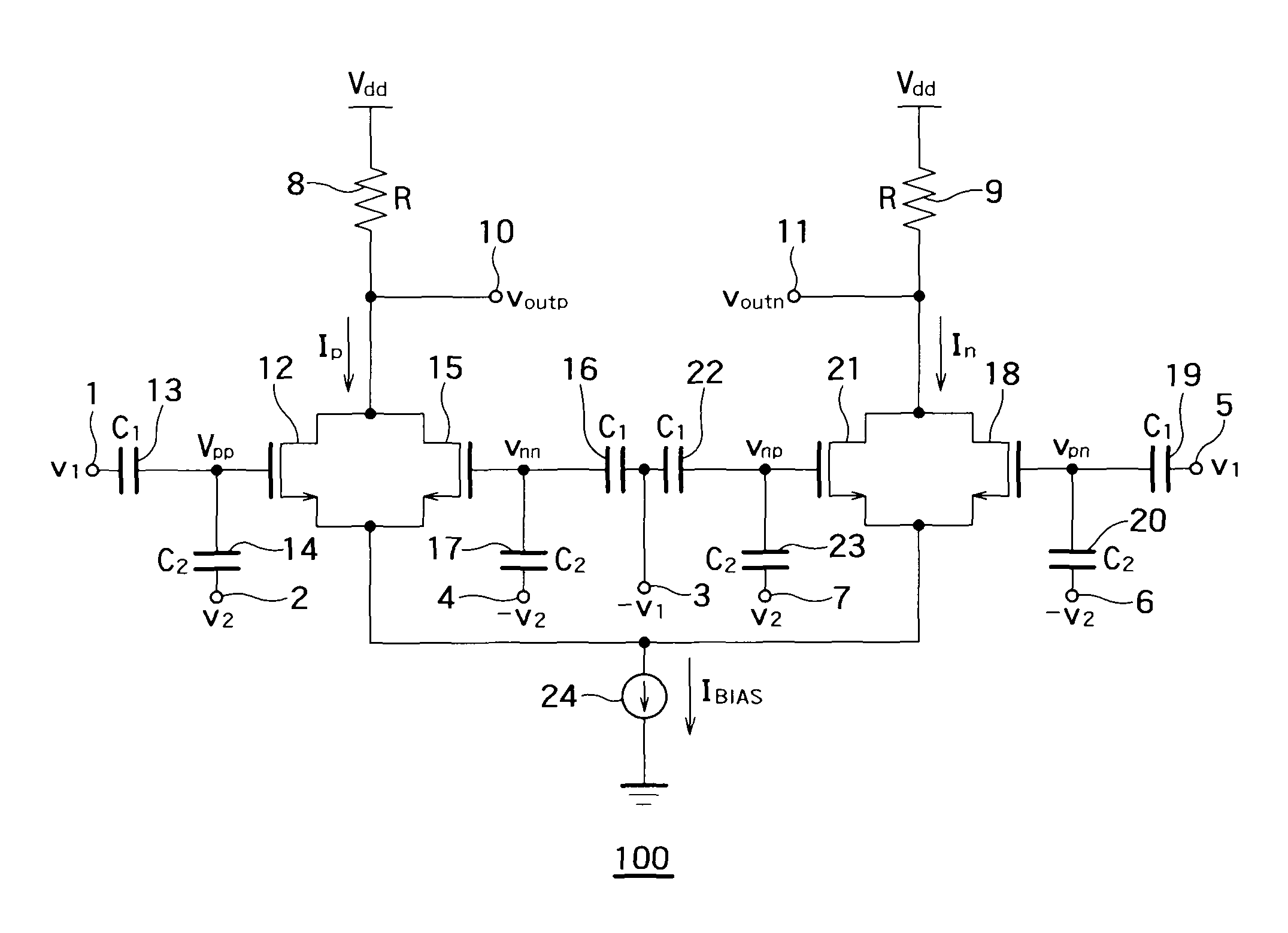
[0119]The present embodiment will describe an example of a mixer circuit in which analog signals inputted to input terminals are added by capacitive coupling. In the present embodiment, the addition of the analog signals by capacitive coupling is used and the square-law characteristics of the drain current of a MOS transistor operating in a saturated region are used. With this configuration, the voltage and power of the mixer circuit can be reduced.

[0120]Further, in the present embodiment, a first potential is a power supply potential and a second potential is a ground potential. Moreover, MOS transistors are n-type MOS transistors. The control electrodes of the transistors correspond to the gate electrodes of the MOS transistors.

[0121]On the gate of each MOS transistor, a DC voltage is biased but is canceled in the examination of output characteristics. Thus a direct current is not considered in the present embodiment.

[0122]Particularly in a radio transmitter, undesired spuriousnes...

second embodiment

[0171]The first embodiment described an example of the configuration of the mixer circuit.

[0172]The mixer circuit of the first embodiment can achieve the same effect even when the polarity of the circuit is inverted.

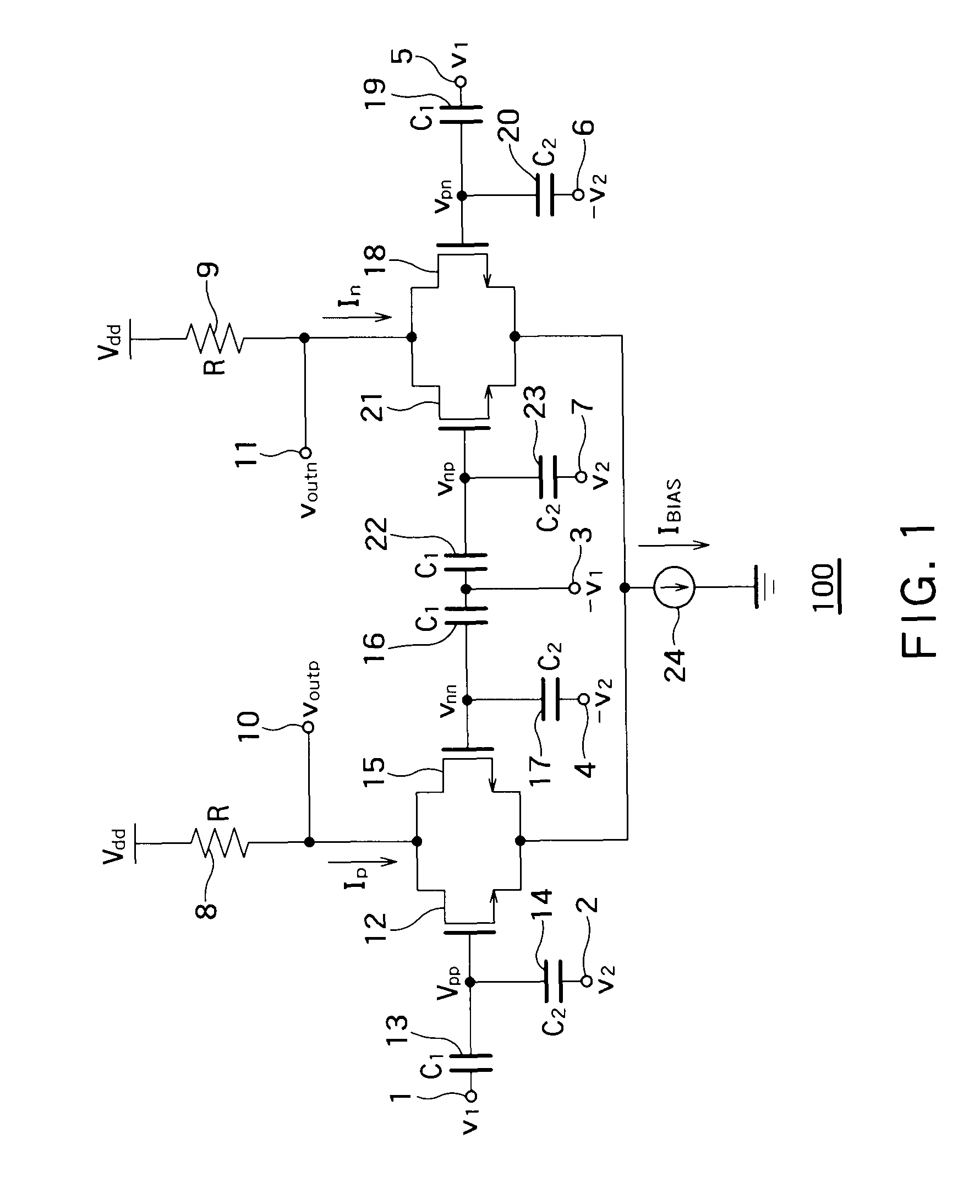
[0173]The present embodiment will describe a structural example of a mixer circuit whose polarity is inverted from the circuit of the first embodiment.

[0174]As described above, the polarity of the circuit is inverted in the present embodiment, so that a first potential is a ground potential and a second potential is a power supply potential. Moreover, MOS transistors are p-type MOS transistors. The control electrodes of the transistors correspond to the gate electrodes of the MOS transistors.

[0175]As in the first embodiment, a DC voltage is biased to the gates of the MOS transistors but is canceled in the examination of output characteristics. Thus a direct current is not considered in the present embodiment.

[0176]FIG. 2 is a circuit diagram showing the main configuratio...

third embodiment

[0212]The first and second embodiments described examples of the configuration of the mixer circuit.

[0213]In the first and second embodiments, for example, resistance loads are used as the first and second resistor circuits of the mixer circuits. Transistors may be used as the first and second resistor circuits.

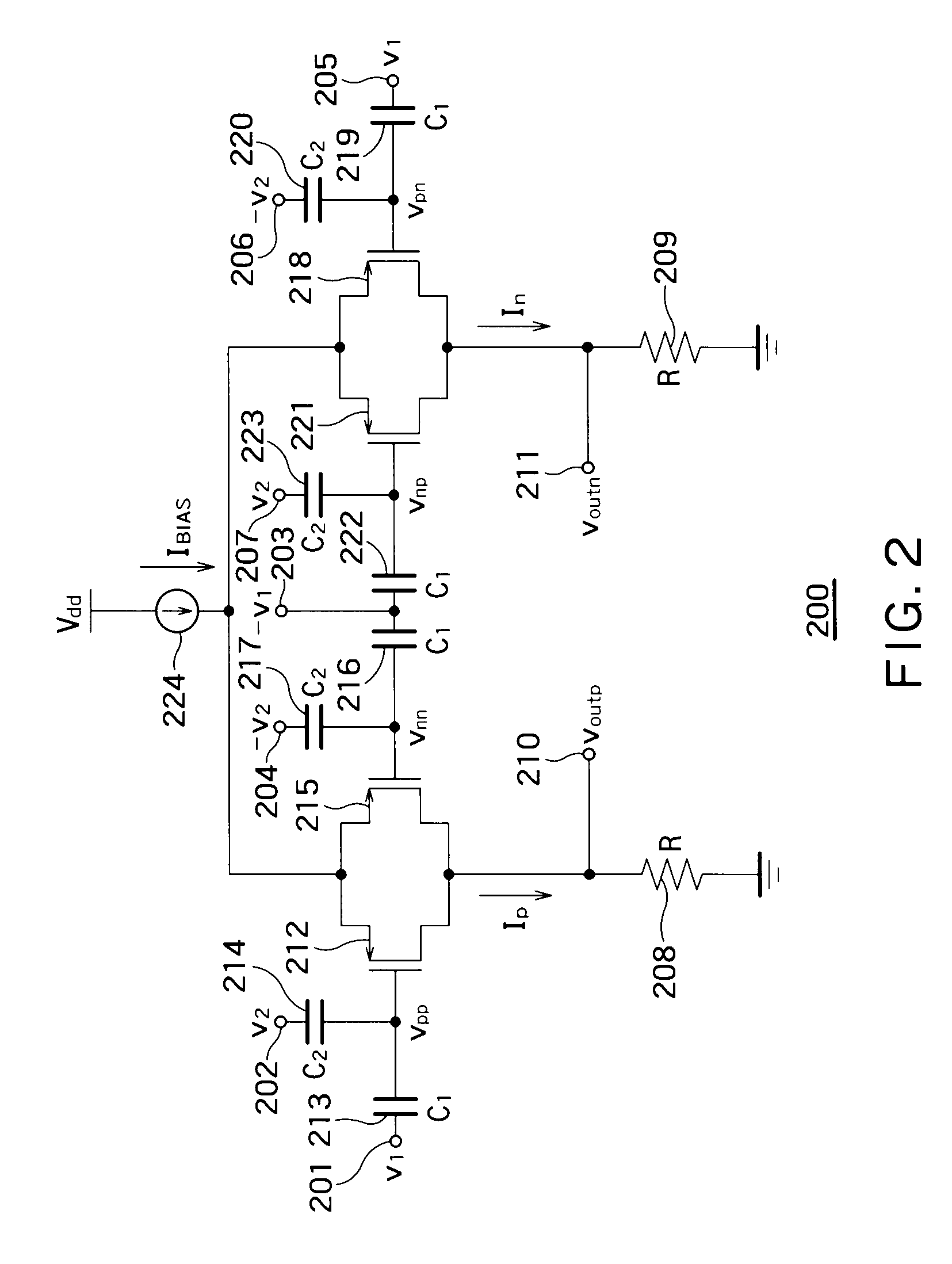
[0214]The present embodiment will describe a structural example of a mixer circuit using transistors as first and second resistor circuits. In this example, transistors are used as the first and second resistor circuits of the mixer circuit described in the first embodiment.

[0215]As in the first embodiment, a DC voltage is biased to the gates of the MOS transistors but is canceled in the examination of output characteristics. Thus a direct current is not considered in the present embodiment.

[0216]FIG. 3 is a circuit diagram showing the main configuration of the mixer circuit according to a third embodiment which is an aspect of the present invention. Configurations indicated ...


PUM


Abstract

In a mixer circuit, addition of analog signals by capacitive coupling is used and square-law characteristics of the drain current of a MOS transistor operating in a saturated region are used. With this configuration, the voltage and power of the mixer circuit can be reduced.

Description

BACKGROUND OF THE INVENTION[0001]1. Field of the Invention[0002]The present invention relates to a mixer circuit used for a large scale integration (LSI) for radio communications.[0003]2. Background Art[0004]In radio communications of the prior art, mixer circuits for frequency converting radio frequency (RF) signals have been used.[0005]As technology scaling arises with the development of CMOS process technology, a reduction in power supply voltage has become a serious problem in the design of future RF analog circuits. Further, since RF analog circuits have been increasingly mounted in portable equipment, another significant challenge is to operate LSIs for radio communications, on which RF analog circuits are mounted, with low power.[0006]However, the mixer circuits used for LSIs according to the prior art have been mainly made up of MOS transistors stacked in two stages or more, so that the mixer circuits of the prior art are not suitable for low-voltage operations.[0007]In orde...

Claims


Application Information

Patent Timeline
Patent Type & Authority Patents(United States)
IPC IPC(8): G06G7/44
CPCH03D7/1441H03D7/1458H03D7/1433H03D7/165H03D2200/0043H03D2200/0084
Inventor DEGUCHI, JUN
Owner KIOXIA CORP
Why Eureka
Try Eureka