Optical recording medium

a technology of optical recording medium and optical recording medium, which is applied in the direction of mechanical recording, line-transmission details, instruments, etc., can solve the problems of increasing the interference effect, reducing the exactness of data reproduction, and reducing the quantity of other reflected light that interferes, etc.

Inactive Publication Date: 2010-11-02
TDK CORPARATION
View PDF11 Cites 4 Cited by
  • Summary
  • Abstract
  • Description
  • Claims
  • Application Information

AI Technical Summary

Benefits of technology

[0008]Upon diligent investigations through processes which lead to the conception of the present invention, the inventors ascertained that reductions in the exactness of reproduction of data on an optical recording medium was mainly due to the interference of reflected light other than the regular reflected light for reproduction. In other words, the laser light for reproduction that is irradiated onto the optical recording medium is not only reflected on the information layer of the reproduction target but one portion of that light is also reflected in various states between multiple information layers and interferes with the regular reflected light for reproduction that is reflected on the information layer of the reproduction target. In particular, if the lengths of the regular light path of the laser light for reproduction that is reflected on the information layer of the reproduction target only one time and another light path of the laser light in another reflection state coincide with each other within the optical recording medium, the effect of the interference will become larger. On the other hand, because the thickness of each layer of the optical recording medium has microscopic variations in the circumferential direction, the position where the effect of the interference is large and the position where the effect of the interference is small in the circumferential direction become intermixed. Consequently, it is thought that variations in the reflectance become larger each time around and the exactness of reproduction of the data is reduced.
[0009]In contrast to the regular reflected light for reproduction being incident from the cover layer side on the information layer of the reproduction target and then reflected toward the cover layer side one time only as described above, other reflected light that interferes with this light is reflected multiple times between multiple information layers and is always incident from the substrate side on any of the information layers and is then reflected toward the substrate side at least one time. Therefore, by making the reflectance of the information layer on the substrate side lower than the reflectance of the information layer on the cover layer side, quantity of other reflected light that interferes with the regular reflected light for reproduction is reduced. Consequently, the exactness of reproduction of the data can be improved.

Problems solved by technology

In other words, the laser light for reproduction that is irradiated onto the optical recording medium is not only reflected on the information layer of the reproduction target but one portion of that light is also reflected in various states between multiple information layers and interferes with the regular reflected light for reproduction that is reflected on the information layer of the reproduction target.
In particular, if the lengths of the regular light path of the laser light for reproduction that is reflected on the information layer of the reproduction target only one time and another light path of the laser light in another reflection state coincide with each other within the optical recording medium, the effect of the interference will become larger.

Method used


Image

  • Optical recording medium
  • Optical recording medium
  • Optical recording medium

Examples


working example 1

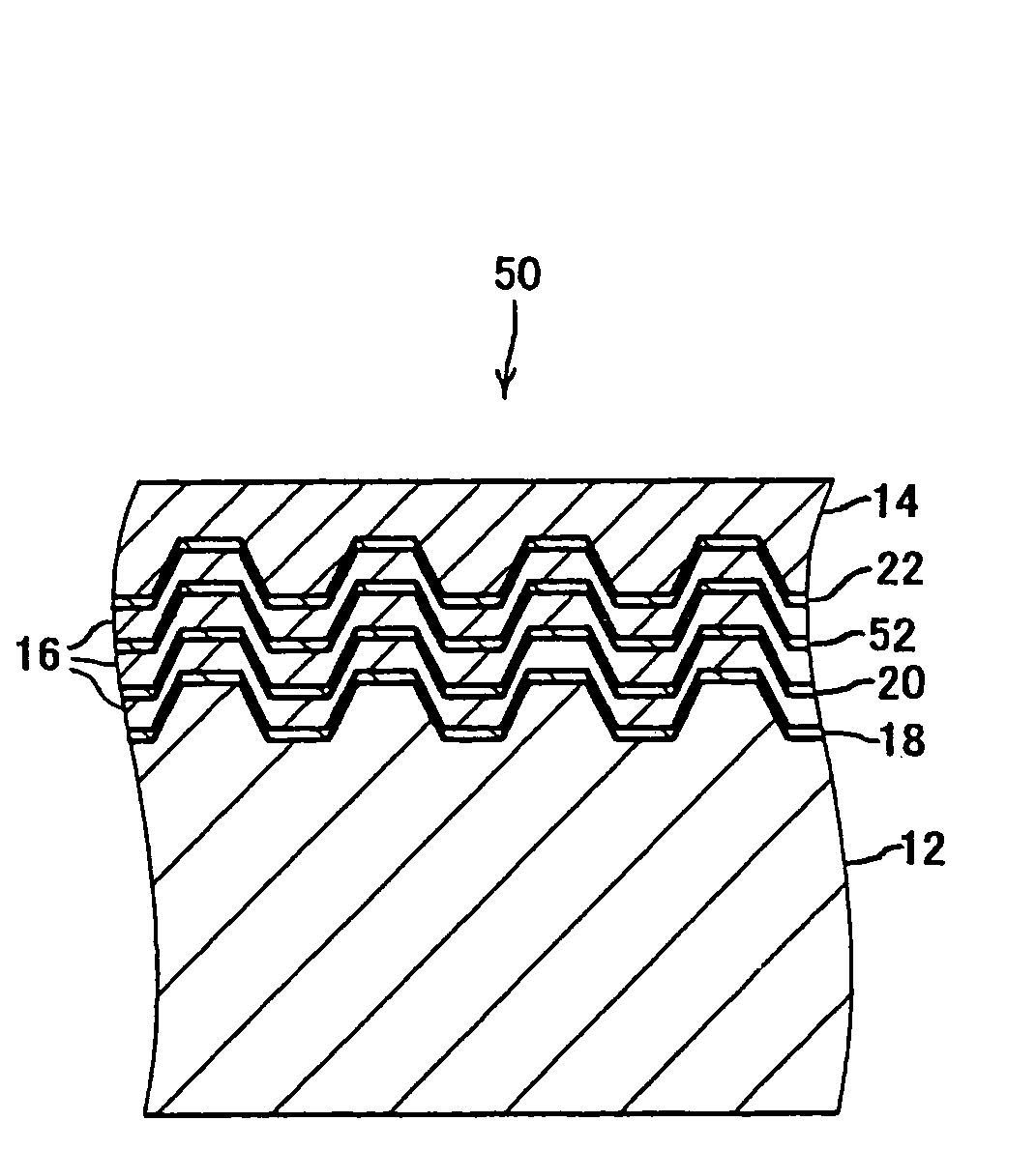
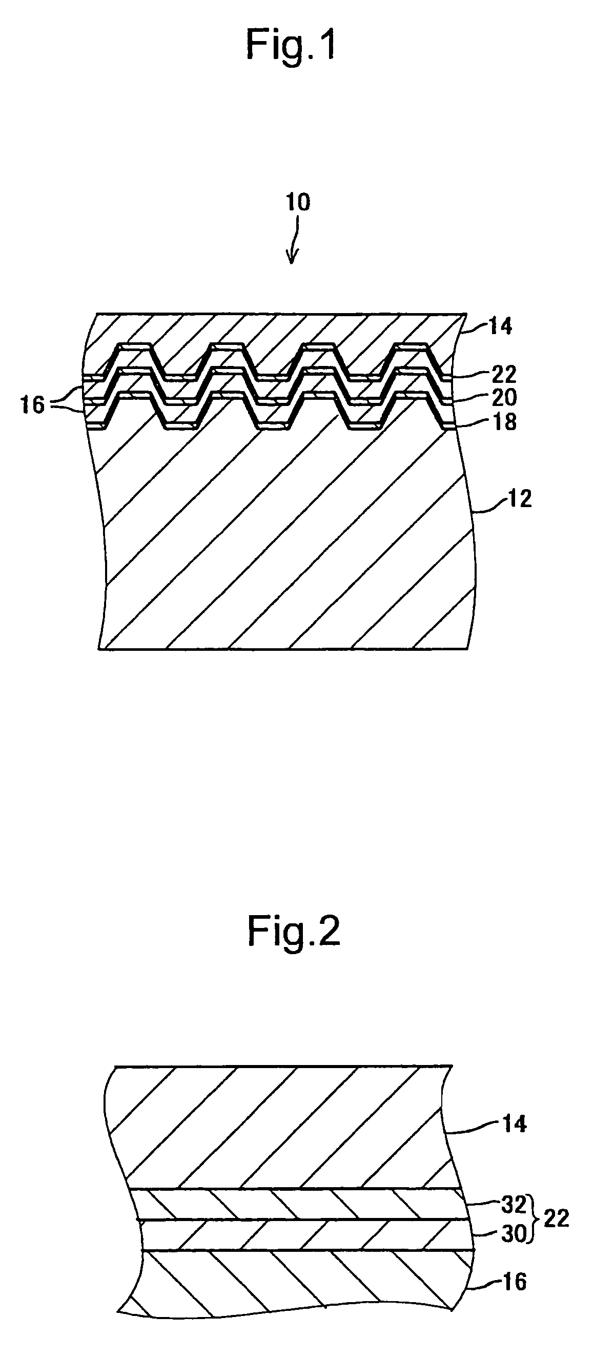
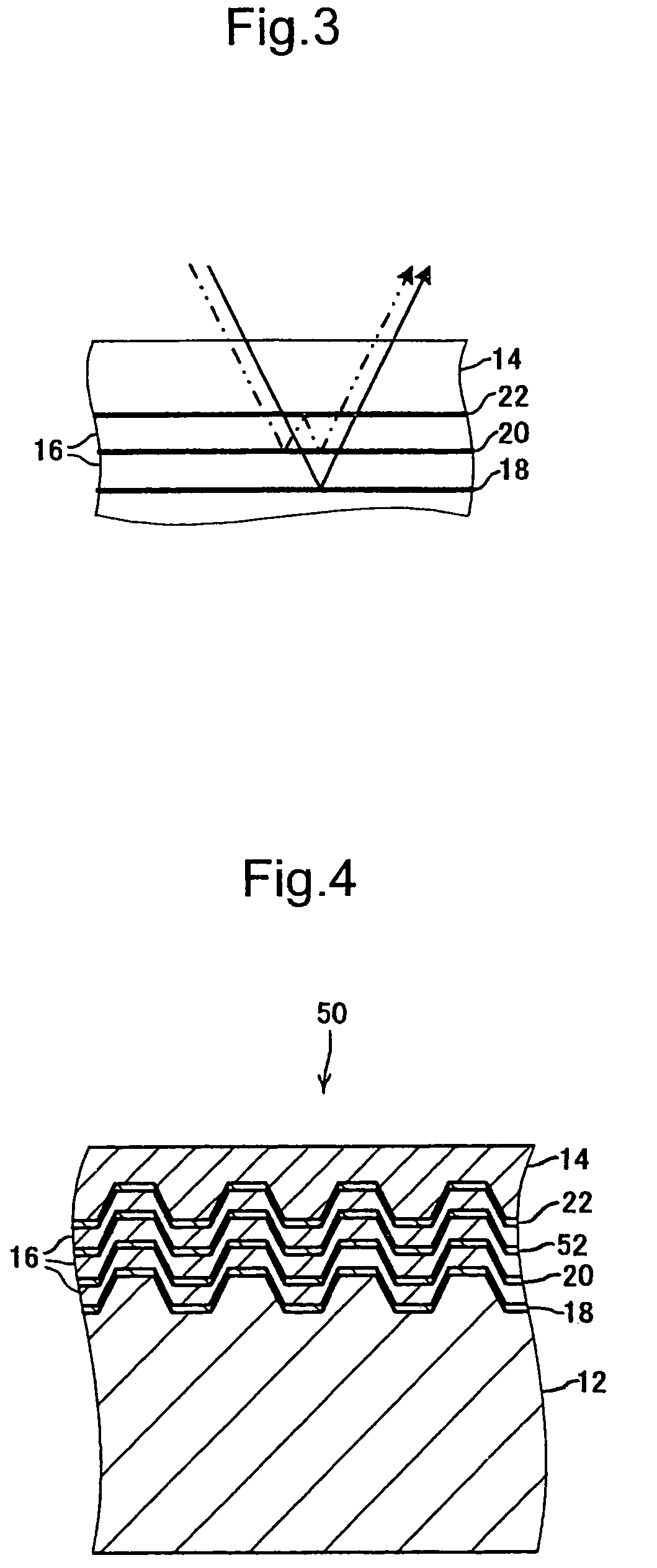
[0048]Three optical recording media A, B, C were produced. These optical recording media were R-type with three recording layers and had configurations equal to optical recording medium 10 of the first exemplary embodiment. These three optical recording media A, B, and C each had the mutually different configuration of the information layer 22. The configuration, with the exception of the information layer 22, was equal.

[0049]In more detail, the information layer 22 of the optical recording medium A comprises a recording layer of Zn20Si10Mg25O20S25 (mole ratio) material and a dielectric layer of ZnSSiO2 material arranged on the cover layer 14 side of this recording layer. The thickness of the recording layer was approximately 18 nm and the thickness of the dielectric layer was approximately 60 nm.

[0050]Further, the information layer 22 of the optical recording medium B comprises a recording layer of Zn20Si10Mg25O20S25 material and a dielectric layer of Al2O3 material arranged on the...

working example 2

[0066]An optical recording medium F was produced. This optical recording medium F was a ROM type with three recording layers and has a configuration equal to the optical recording medium 10 of the first exemplary embodiment.

[0067]In more concrete terms, the information layer 22 of the optical recording medium F comprises a reflective layer formed from Al material deposited on the concavo-convex pattern of the substrate 12 and a dielectric layer of ZnSSiO2 material arranged on the cover layer 14 side of this reflective layer. The thickness of the reflective layer was approximately 2.5 μm. The optical absorbance of Al is approximately 15%. Table 2 shows the configurations of the information layers 18, 20, and 22 and the spacer layer 16 of the optical recording layer F.

[0068]

TABLE 2Opticalrecording mediumFGInformationReflective layerMaterialAllayer 22Thickness(nm)2.5Dielectric layerMaterialZnS•SiO2—Thickness(nm)32—Spacer layer 16MaterialAcrylic UVcurable resinThickness(nm)20Information...


PUM

PropertyMeasurementUnit
reflectanceaaaaaaaaaa
thicknessaaaaaaaaaa
diameteraaaaaaaaaa

Abstract

An optical recording medium has a plurality of information layers which are placed between a substrate and an optically transparent cover layer with optically transparent spacer layers interposed between the information layers. From among the plurality of information layers, the information layer excluding the information layer arranged closest to the substrate and the information layer adjacent to the information layer closest to the substrate has asymmetrical reflection characteristics in which reflectance on the substrate side when light incident from the substrate side is reflected on the information layer toward the substrate side is lower than the reflectance on the cover layer side when light incident from the cover layer side is reflected on the information layer toward the cover layer side.

Description

BACKGROUND OF THE INVENTION[0001]1. Field of the Invention[0002]The present invention relates to an optical recording medium comprising a plurality of information layers which are placed between a substrate and an optically transparent cover layer with optically transparent spacer layer interposed between the information layers.[0003]2. Description of the Related Art[0004]Optical recording media, such as CDs (Compact Disc) and DVDs (Digital Versatile Disc), have been widely utilized as information recording media. Furthermore, in recent years optical recording media with even higher densities that can record large quantities of information by means of using blue or blue-violet laser light as the irradiation light have been gathering attention. Moreover, these optical recording media can increase the recording capacity to that extent by providing a configuration comprising a plurality of information layers which are placed between a substrate and an optically transparent cover layer ...

Claims


Application Information

Patent Timeline
Patent Type & Authority Patents(United States)
IPC IPC(8): G11B7/20H04B1/56H04B3/40H04B3/20H04L5/14
CPCG11B7/2403G11B7/242G11B7/243G11B7/24038G11B7/2585G11B2007/24304G11B2007/24312G11B2007/2432G11B2007/24324
Inventor MISHIMA, KOJIYOSHITOKU, DAISUKETSUKAGOSHI, TAKUYA
Owner TDK CORPARATION
Why Eureka
Try Eureka