Energy conserving active thermal insulation

a passive insulation and energy saving technology, applied in the field of active thermal insulation, can solve the problems of cumbersome phase change material and containment, inability to disclose the treatment of an external wall with structural openings, and inherently unrestricted ceilings beneath the attic space for additional passive insulation, etc., to achieve the effect of improving the thermal resistance r of the building structure, and reducing the risk of leakag

Inactive Publication Date: 2010-11-09
ACTIVE INSULATION
View PDF38 Cites 9 Cited by
  • Summary
  • Abstract
  • Description
  • Claims
  • Application Information

AI Technical Summary

Problems solved by technology

Ceilings beneath the attic space are inherently unrestricted for additional passive insulation.
The U.S. Pat. No. 5,761,864 patent does not disclose the treatment of an external wall with structural openings.
The phase change material and containment are cumbersome because the material changes from solid to liquid and back again.

Method used


Image

  • Energy conserving active thermal insulation
  • Energy conserving active thermal insulation
  • Energy conserving active thermal insulation

Examples


Embodiment Construction

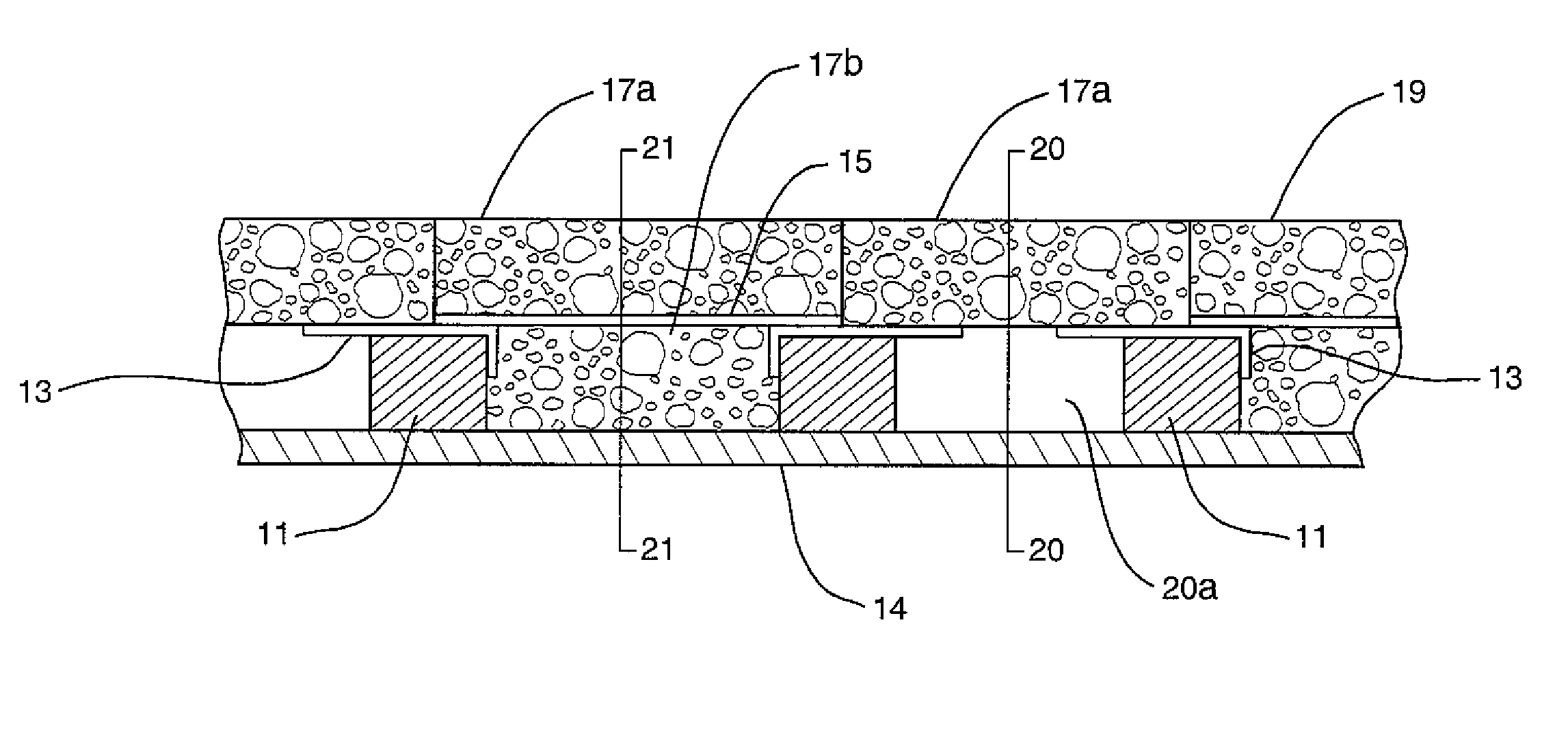
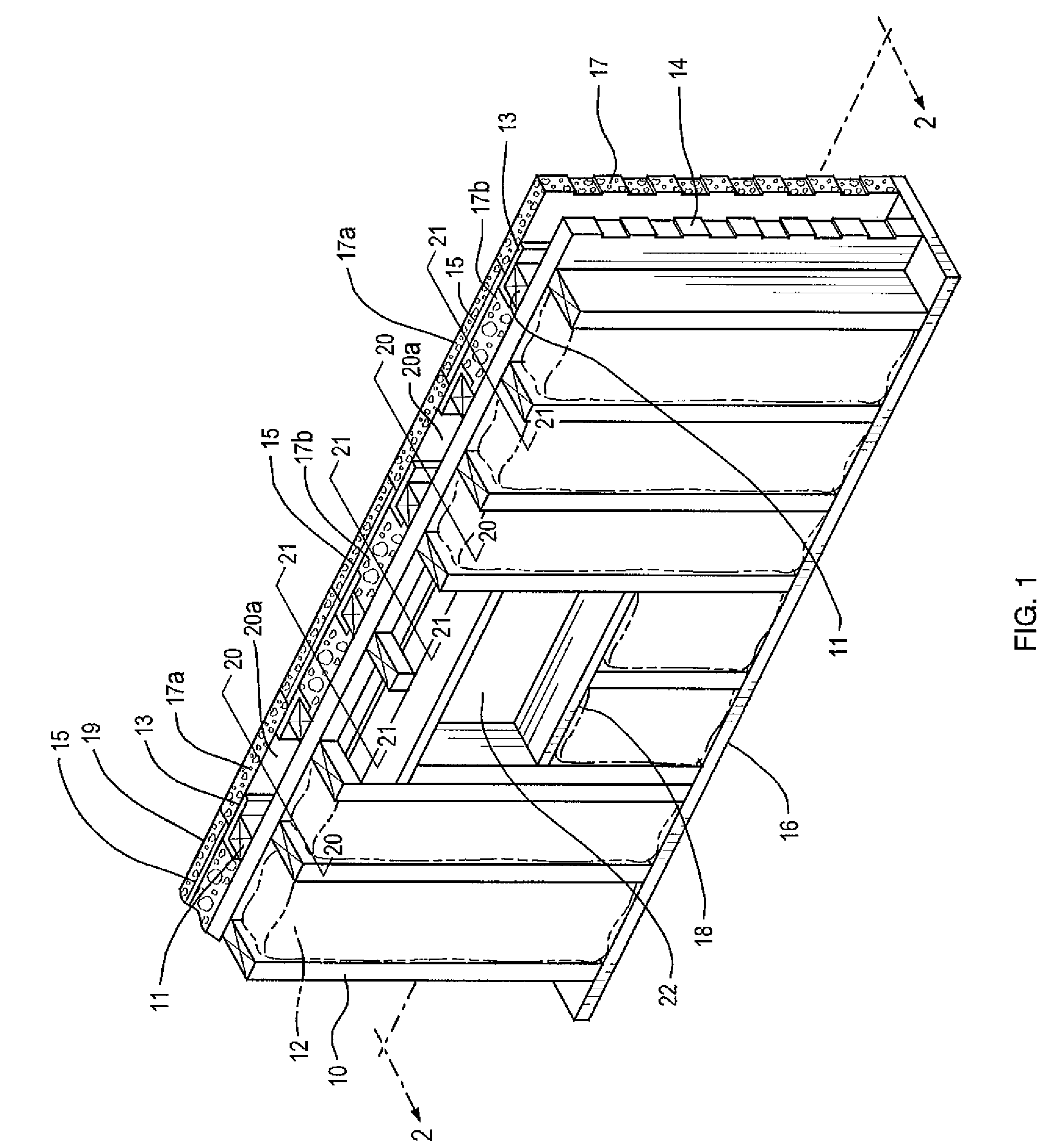
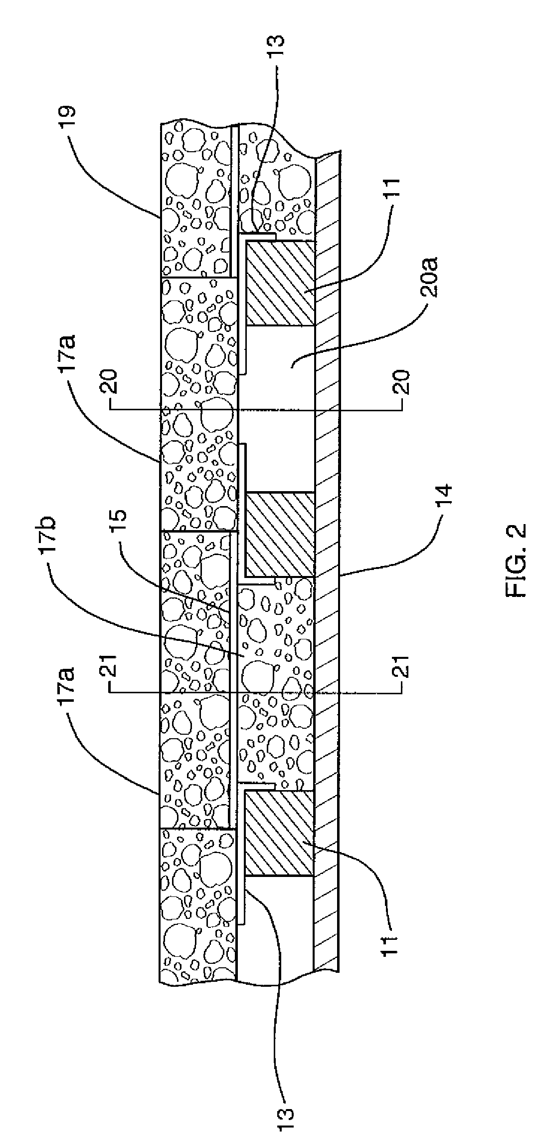
[0036]FIG. 1 shows a partial isometric view of an active insulation structure of the present invention. The active insulation structure establishes one or more air channels 20 and one or more thermally conductive ply channels 21. As shown in the representative illustration of FIG. 1, the active insulation structure is shown installed upon the exterior surface of the exterior sheeting 14 forming part of a building structure to be insulated, with the air channels 20 located outside of and adjacent to both sides of a window opening 22. The window opening 22 is formed between wall studs 10 and transverse studs 18. The exterior sheeting 14 is fastened to the wall studs 10 and a base plate 16 of the structure to be insulated. The air channel 20 extends from the base to the top of the wall in areas of the structure where the airflow is not obstructed by windows and / or other openings. The air channel 20 is formed between first layer of insulation 17a, preferably a low-density foam but not l...


PUM


Abstract

An energy conserving active thermal insulation arrangement installed upon the ambient surface of an insulated structure employing alternately spaced insulated air channels and insulated conductive ply channels. A thin conductive ply conveys the energy by conduction from the airflow into the adjacent conductive ply channels, that contain an additional layer of foam which improves the conservation of energy. The conductive ply is placed above and below structural openings which would otherwise restrict airflow. The airflow is drawn from beneath the frost line, exhaust ventilation or sunspace. A math model solution determines the energy necessary to maintain a desired room temperature for each hour of the day which characterizes the thermal resistance. As the ambient temperature fluctuates, the resistance varies, however the energy for 24 hours is used to determine the total apparent resistance. Examples of apparent resistance R-value have been improved beyond any published resistance values to date.

Description

CROSS REFERENCE TO RELATED APPLICATION[0001]The present application claims the priority benefit of U.S. provisional patent application Ser. No. 60 / 692,512, filed Jun. 21, 2005, entitled “INSUL-PLY THE ORIGINAL HEAT CONVEYOR ACTIVE INSULATION” of the same named inventors. The entire contents of that prior application are incorporated herein by reference.BACKGROUND OF THE INVENTION[0002]1. Field of the Invention[0003]The present invention relates to an active thermal insulation and its ability to conserve energy by improving the thermal resistance, R, of an insulated structure beyond known values published to date.[0004]2. Description of the Prior Art[0005]Building structures built for human occupancy contain heating and cooling equipment to maintain a desired level of comfort. Insulation is placed in the walls, floors and ceilings of the building envelope. Insulation material relies upon trapped air within or about the material. It is a passive material with a fixed thermal resistanc...

Claims


Application Information

Patent Timeline
Patent Type & Authority Patents(United States)
IPC IPC(8): E04H12/28E04B7/00
CPCE04B1/74E04F13/007F24J2/0444Y02B10/20F24S20/66
Inventor CAMPISI, FRANCIS H.CAMPISI, JAMES F.
Owner ACTIVE INSULATION
Why Eureka
Try Eureka