Hydraulic system

a technology of hydraulic system and throttling method, applied in the direction of fluid coupling, servomotor, coupling, etc., can solve the problems of high initial cost and increase in efficiency over throttling method

Inactive Publication Date: 2010-11-09
DEERE & CO
View PDF56 Cites 80 Cited by
  • Summary
  • Abstract
  • Description
  • Claims
  • Application Information

AI Technical Summary

Benefits of technology

[0006]The present invention provides a hydraulic system control for use with a ground engaging vehicle.

Problems solved by technology

Hydrostatic systems result in an increase in efficiency over the throttling method, but at a high initial expense.

Method used


Image

  • Hydraulic system
  • Hydraulic system
  • Hydraulic system

Examples


Embodiment Construction

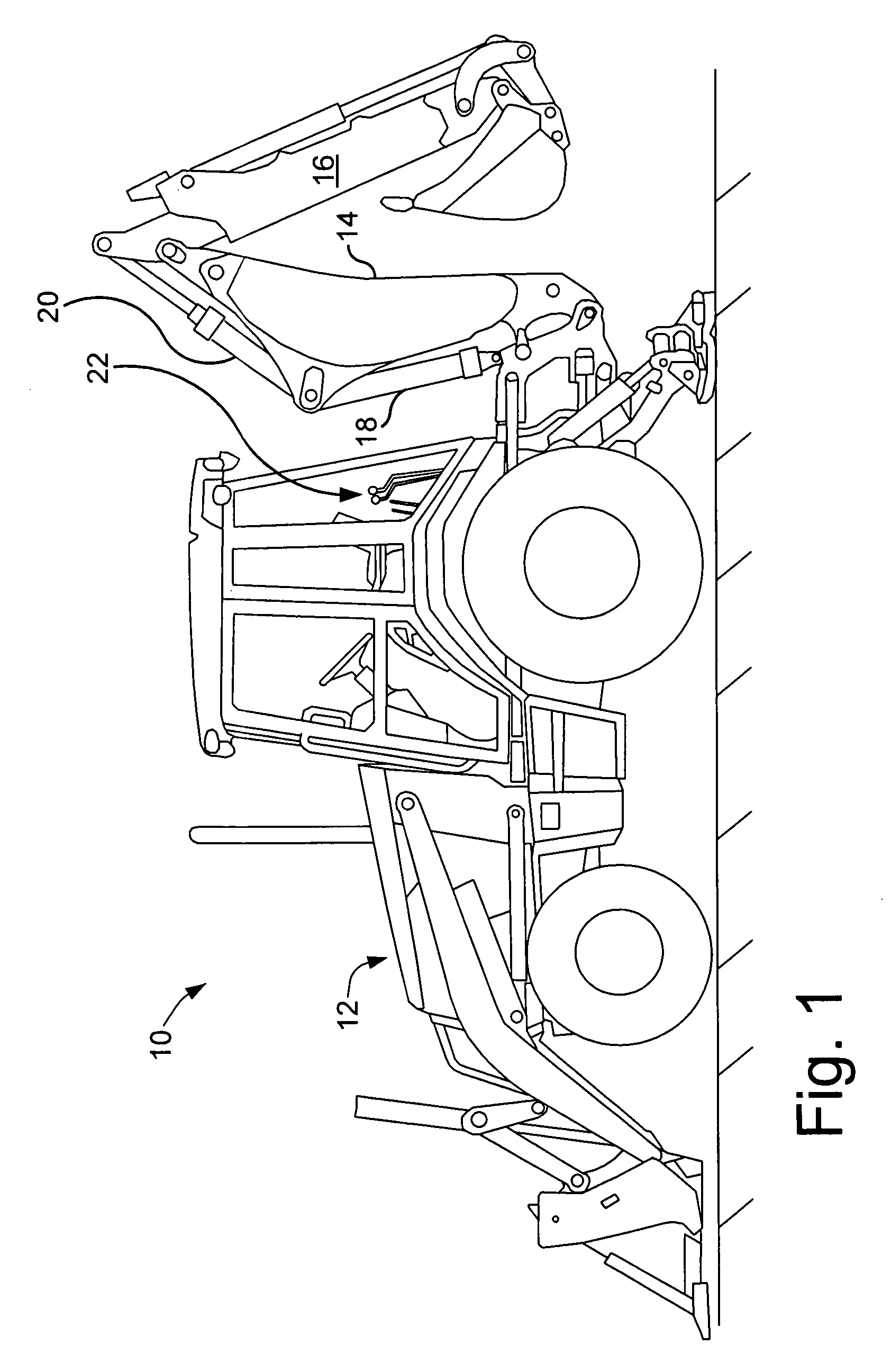
[0014]Referring now to the drawings, and more particularly to FIG. 1, there is shown a ground engaging vehicle 10, more particularly illustrated as a backhoe / loader 10 having an engine 12, a movable arm 14, a moveable arm 16, a hydraulic cylinder 18, a hydraulic cylinder 20 and control levers 22. Vehicle 10 includes a hydraulic system control that is more precisely described in the following discussion that is driven by engine 12. The hydraulic system providing power to move movable arms 14 and 16 by way power provided to hydraulic cylinders 18 and 20 and under the control of an operator by way of control levers 22.

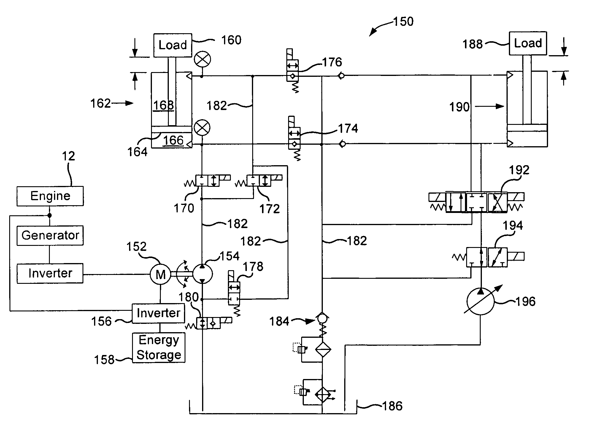
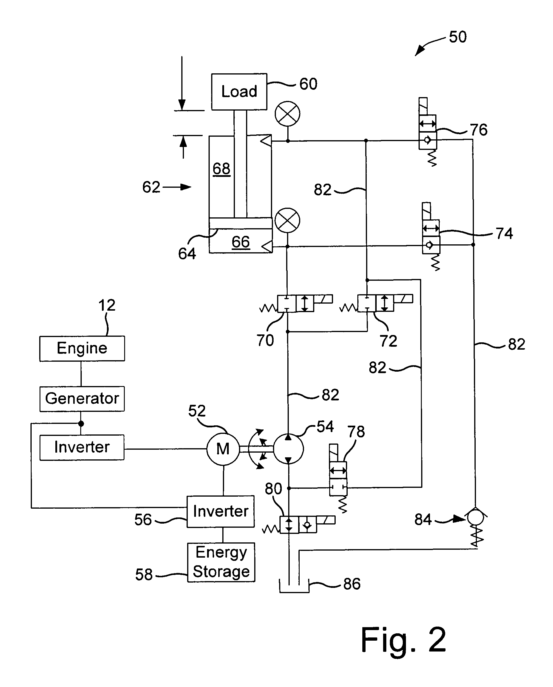
[0015]Referring additionally now to FIG. 2, there is shown a schematic illustration of system 50 that includes an electrical hydraulic control of a typical hydraulic actuator such as a hydraulic cylinder 18 or 20. For ease of illustration, the hydraulic cylinder utilized in the schematics generically refer to any hydraulic cylinder utilized on vehicle 10, not just to cyli...


PUM


Abstract

A ground engaging vehicle including a movable member, a hydraulically driven actuator, a hydraulic pump, a plurality of valves and at least one hydraulic conduit. The hydraulically driven actuator is coupled to the movable member and the actuator has a first chamber and a second chamber. The plurality of non-proportional valves include a first valve, a second valve, a third valve and a fourth valve. The at least one hydraulic conduit couples the pump with the first valve and the second valve. The first valve is in direct fluid communication with the first chamber. The second valve is in direct fluid communication with the second chamber. The third valve is in direct fluid communication with the first chamber and the fourth valve is in direct fluid communication with the second chamber. The first valve and the second valve each include an open position and a closed position.

Description

FIELD OF THE INVENTION[0001]The present invention relates to a hydraulic system, and more particularly, to a ground engaging vehicle utilizing a hydraulic control system.BACKGROUND OF THE INVENTION[0002]Hydraulics has a history practically as old as civilization itself. Hydraulics, more generally, fluid power, has evolved continuously and been refined countless times into the present day state in which it provides a power and finesse required by the most demanding industrial and mobile applications. Implementations of hydraulic systems are driven by the need for high power density, dynamic performance and maximum flexibility in system architecture. The touch of an operator can control hundreds of horsepower that can be delivered to any location where a pipe can be routed. The positioning tolerances can be held within thousandths of an inch and output force can be continuously varied in real time with a hydraulic system. Hydraulics today is a controlled, flexible muscle that provides...

Claims


Application Information

Patent Timeline
Patent Type & Authority Patents(United States)
IPC IPC(8): F15B11/04F15B21/00
CPCE02F9/2203E02F9/2217E02F9/2221F15B2211/20515F15B2211/20538F15B2211/20546F15B2211/20569F15B2211/20576F15B2211/30575F15B2211/3144F15B2211/615F15B2211/62F15B2211/6313F15B2211/6336F15B2211/88
Inventor CHERNEY, MARK J.DOBCHUK, JEFFERY W.
Owner DEERE & CO
Why Eureka
Try Eureka