Gas sensor

a technology of gas sensor and sensor, which is applied in the direction of electrochemical generator, specific gravity measurement, instruments, etc., can solve the problems of detection element contacting with dew condensation, deteriorating the sensitivity of detection element,

Active Publication Date: 2010-11-09
HONDA MOTOR CO LTD
View PDF25 Cites 16 Cited by
  • Summary
  • Abstract
  • Description
  • Claims
  • Application Information

AI Technical Summary

Benefits of technology

[0011]According to the gas sensor, the supporting member that supports the detection element is fixed so as to protrude from the heating element provided on the substrate; therefore, it is possible to directly heat the supporting member and the substrate connected to the detection element. Therefore, while stopping the supply of electrical power to the detection element, it is possible to prevent producing dew condensing at the supporting member and the substrate in addition to the detection element itself. Furthermore, even when the dew condensation is produced at other locations in the gas sensor, it is possible to prevent the dew condensation reaching via the supporting member to the detection element.
[0014]In this case, even when supplying electrical power to the detection element is stopped, since the lead wire and the substrate can be directly heated in addition to the detection element itself, it is possible to prevent producing dew condensation thereon. Furthermore, even when the dew condensation is produced at other locations in the gas sensor, it is possible to prevent the dew condensation reaching to the detection element through the supporting element and the lead wire.
[0016]In these cases, the examination gas will be heated while passing through the heating element having the communication hole or the porous heating element; therefore, it is possible to prevent the temperature of the examination gas introduced into a gas detection chamber from decreasing to equal to or less than the dew point temperature, and thereby preventing producing dew condensation in the gas detection chamber.
[0020]It may be arranged such that an inner surface of a cylinder member that forms the detection chamber is made of a metal plate, and thereby forming an area where a dew condensation is easily produced comparing to another area, at a position away from the detection element.

Problems solved by technology

Therefore, there is a case in which the predetermined necessary heating amount for preventing producing dew condensation inside the gas sensor is insufficient, and thereby causing the detection element contacting with the dew condensation.
In such a situation, if the electrical power is supplied to the detection element, there may be a problem in which the temperature distribution on a surface of the detection element becomes locally uneven, and thereby causing defects such as destruction of the detection element, deteriorating the sensitivity of the detection element, and the like.

Method used


Image

  • Gas sensor
  • Gas sensor
  • Gas sensor

Examples


Embodiment Construction

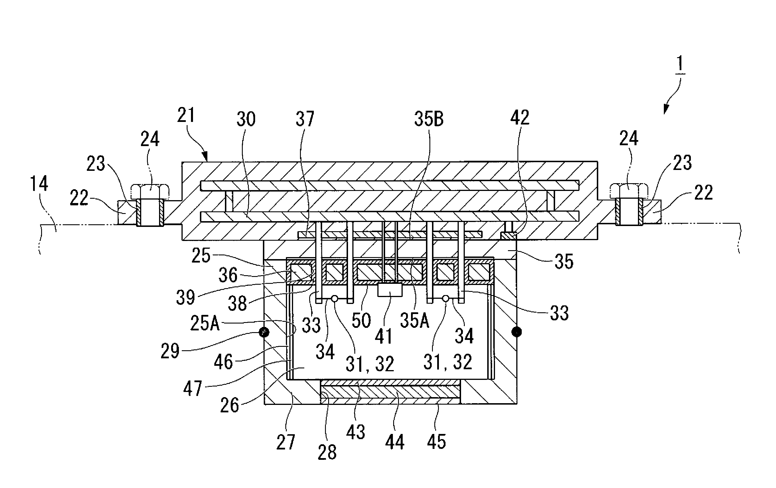
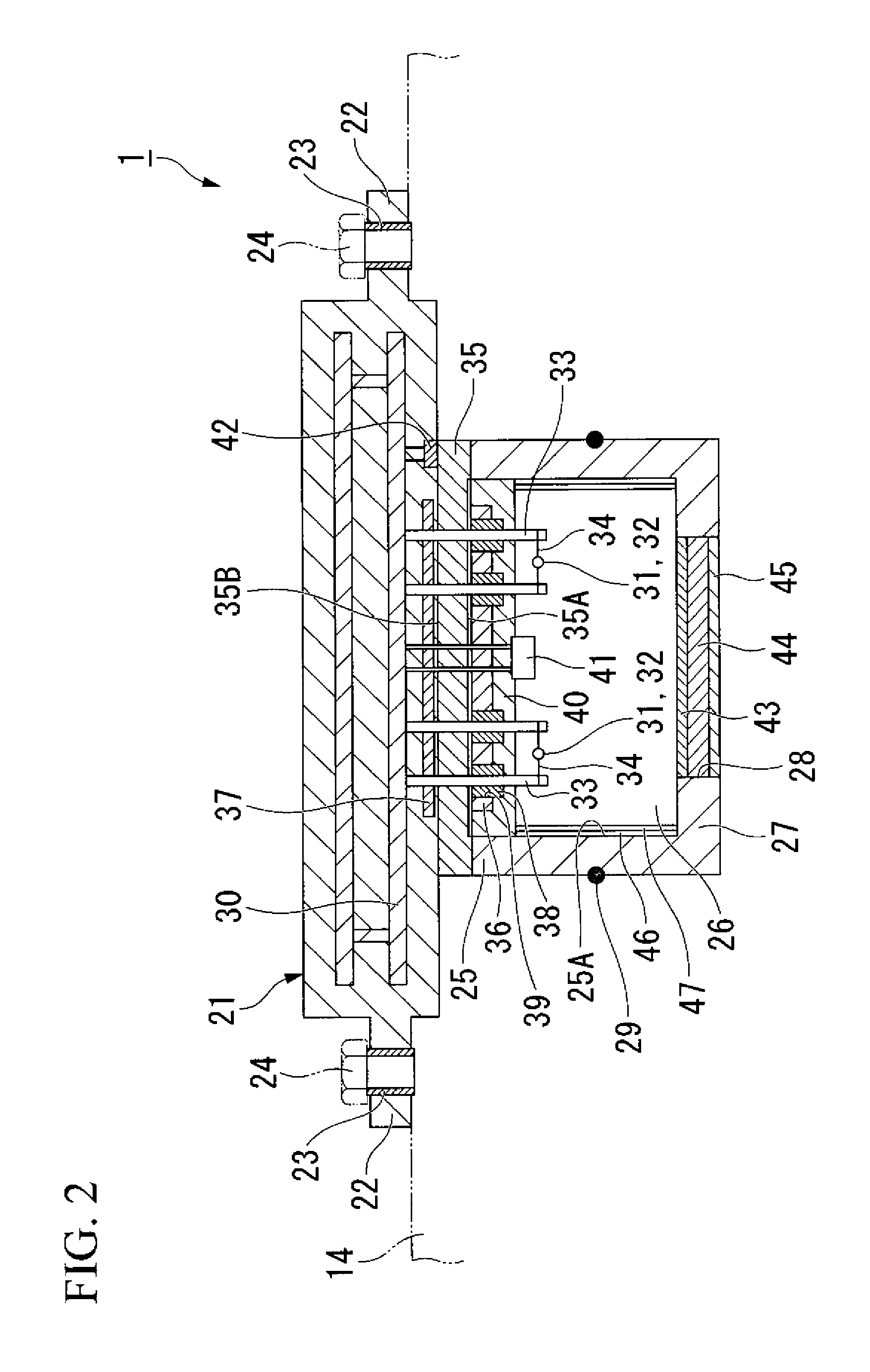
[0031]A gas sensor according to one embodiment of the present invention will be explained below with reference to the drawings.

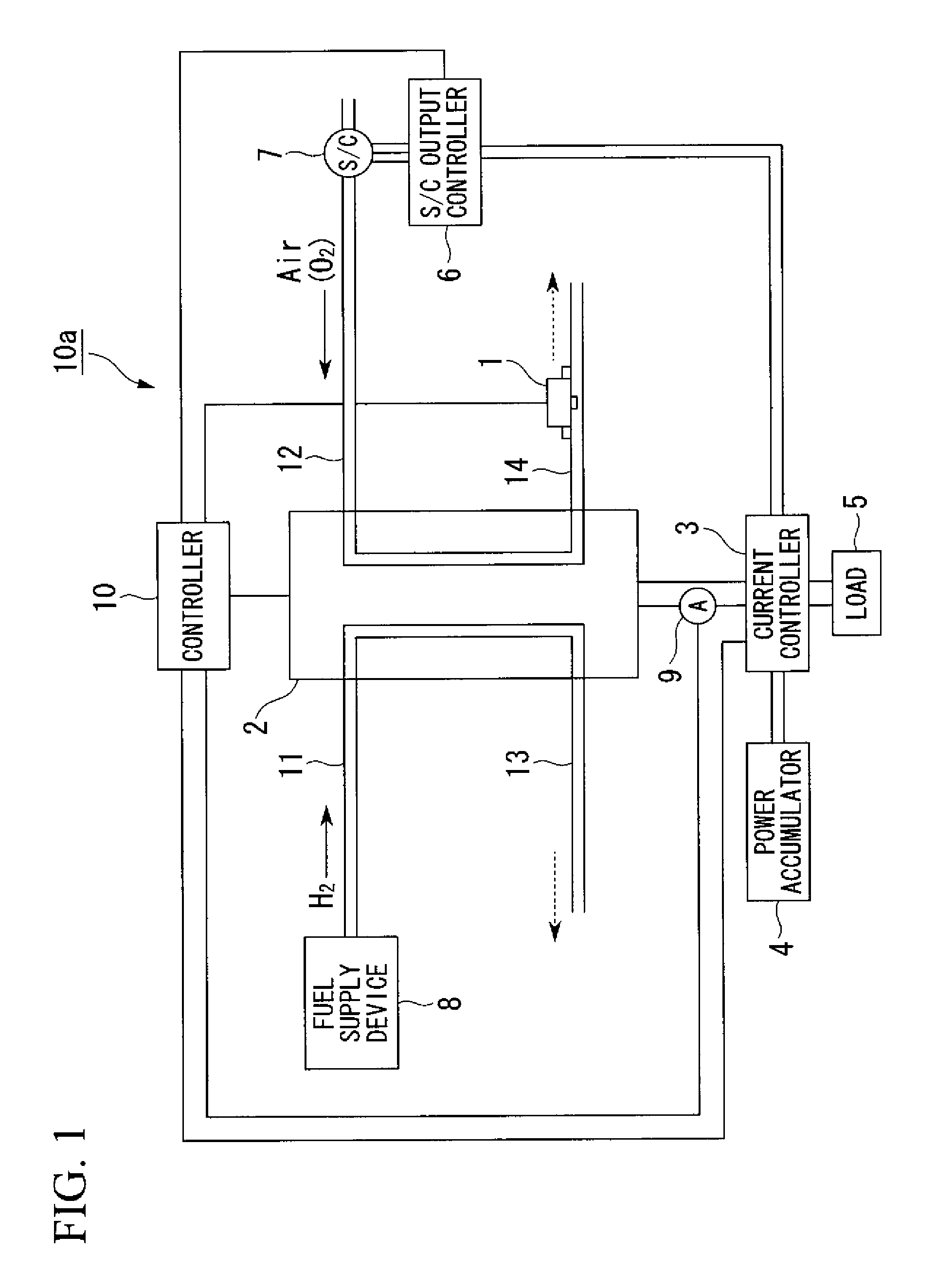
[0032]As shown in for example FIG. 1, a gas sensor 1 of the present embodiment is installed in a fuel cell system 10a. This fuel cell system 10a is provided with a fuel cell 2, a current controller 3, a power accumulator 4, a load 5, an S / C output controller 6, a super charger (S / C) 7, a fuel supply device 8, an output current sensor 9, and a controller 10. Among lines 11, 12, 13, and 14, the gas sensor 1 is provided to the outlet line 14 on an oxygen electrode side.

[0033]The fuel cell 2 is mounted as a driving source in a vehicle such as an electric vehicle. The fuel cell 2 is constituted by a plurality of cells, each cell consisting of an electrolyte electrode structure, in which a solid polymer electrolyte membrane is held between a fuel electrode and an oxygen electrode, and sandwiched by separators.

[0034]Fuel gas containing hydrogen is supplied from the...


PUM

PropertyMeasurementUnit
concentrationaaaaaaaaaa
areaaaaaaaaaaa
temperatureaaaaaaaaaa

Abstract

This gas sensor is provided with: a detection element that measures a gas concentration of a detection target gas contained in an examination gas; a substrate having a heating element; and a supporting member that is fixed to the substrate, protrudes from the heating element, and supports the detection element.

Description

BACKGROUND OF THE INVENTION[0001]Priority is claimed on Japanese Patent Application No. 2006-288565, filed Oct. 24, 2006, the contents of which are incorporated herein by reference.[0002]1. Field of the Invention[0003]The present invention relates to a gas sensor.[0004]2. Description of the Related Art[0005]As an example of a conventional gas sensor which detects inflammable gas contained in an examination gas in a high temperature and high humidity environment, a gas sensor is known which is equipped with a heater unit for preventing a detection element from contacting with dew condensation, and thereby preventing producing the dew condensation inside the gas sensor (for example, refer to Japanese Unexamined Patent Application, First Publication No. H08-121754).[0006]In addition, as another conventional gas sensor that is provided in an exhaust system on an oxygen electrode side of a solid polymer membrane fuel cell, and detects hydrogen gas leaked from a fuel electrode side to the...

Claims


Application Information

Patent Timeline
Patent Type & Authority Patents(United States)
IPC IPC(8): G01N25/00
CPCG01N27/16H01M8/04089H01M8/04455G01N33/0009H01M2250/20Y02E60/50Y02T90/32Y02T90/40
Inventor OISHI, HIDETOSHISASAKI, TAKASHISUZUKI, AKIHIROEGUCHI, TSUYOSHI
Owner HONDA MOTOR CO LTD
Why Eureka
Try Eureka