Eureka AIR delivers breakthrough ideas for toughest innovation challenges, trusted by R&D personnel around the world.

Curve surface glass shaping device and shaping method

A curved glass and forming device technology, applied in glass forming, glass reshaping, glass manufacturing equipment, etc., can solve problems affecting the quality of curved glass forming and difficult control of temperature field, so as to improve yield and process efficiency, The heating and cooling is convenient and easy, and the effect of avoiding mold marks

Pending Publication Date: 2018-09-21
SHENZHEN SUNSHINE LASER & ELECTRONICS TECH CO LTD
View PDF0 Cites 5 Cited by
  • Summary
  • Abstract
  • Description
  • Claims
  • Application Information

AI Technical Summary

Problems solved by technology

Conventional high-temperature furnaces raise the temperature through heat conduction in the furnace, and the temperature field is difficult to control, which affects the quality of curved glass molding

Method used


Image

  • Curve surface glass shaping device and shaping method
  • Curve surface glass shaping device and shaping method
  • Curve surface glass shaping device and shaping method

Examples


Embodiment 1

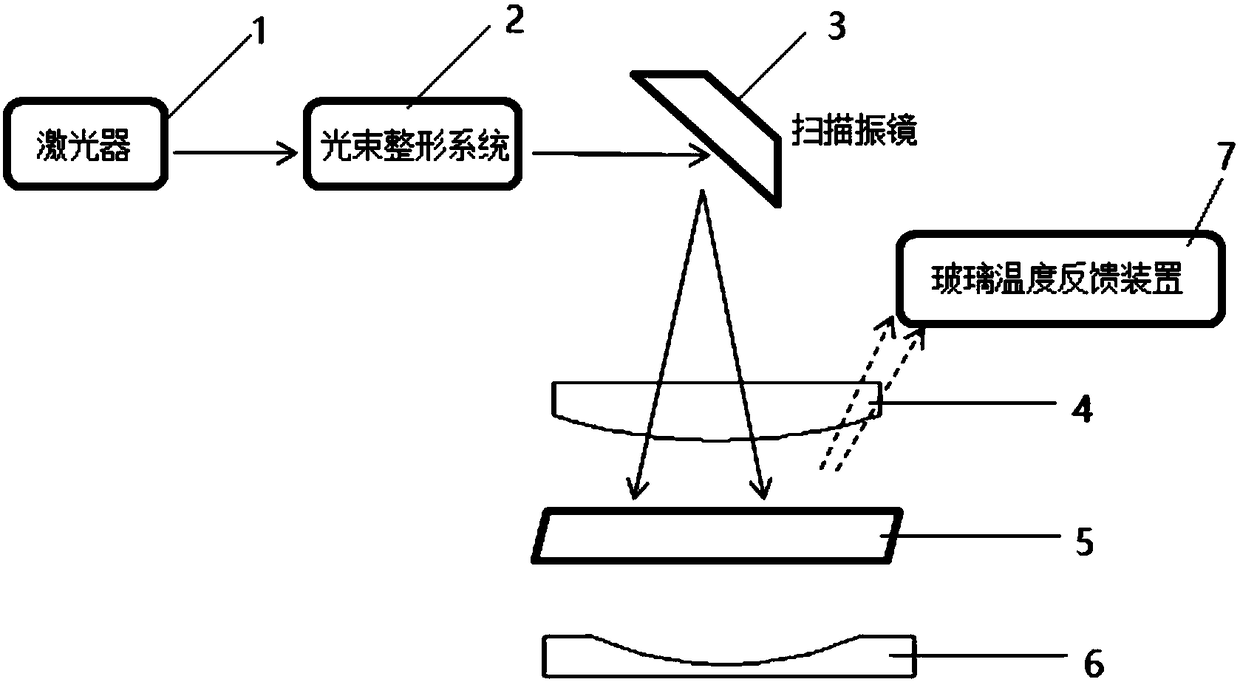
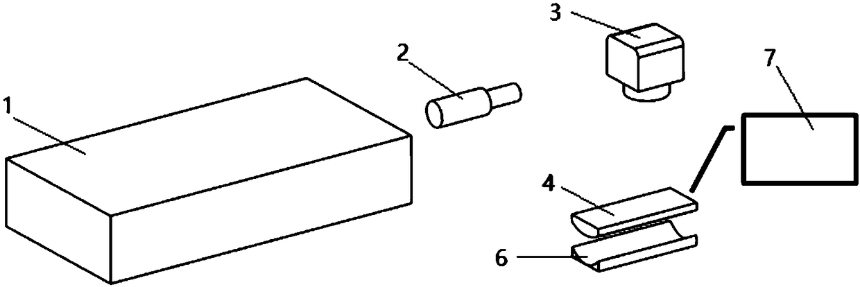
[0050] like figure 1 As shown, a curved glass forming device includes:

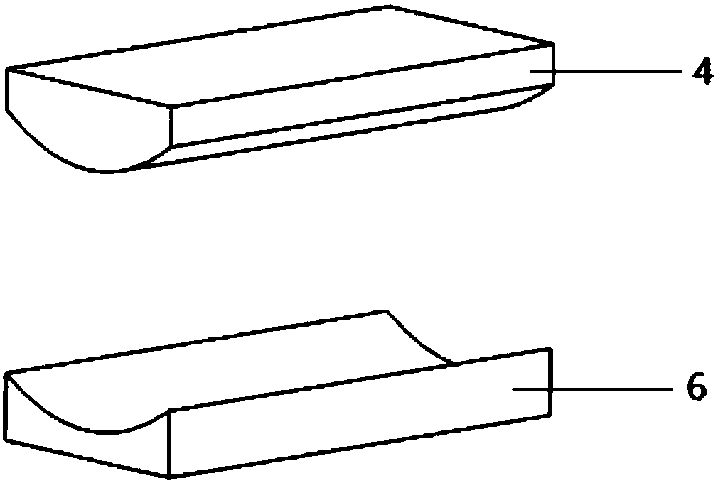
[0051] Laser (including laser control) system, beam shaping system, scanning galvanometer, upper and lower curved surface forming molds, glass temperature feedback device;

[0052] Laser control is connected with the laser, mainly controlling laser power, laser switching and adjusting process parameters, etc.;

[0053] For the above lasers, choose CO with a laser wavelength of 10.6 μm 2 laser;

[0054] The above-mentioned beam shaping system may include a beam expanding lens or a shaping lens group to expand and collimate the laser beam or shape the spot into a circle, ellipse, square, rectangle or other shapes;

[0055] The above-mentioned light spot shaped by the beam shaping system can be circular, square, rectangular or other shapes, preferably a rectangular light spot;

[0056] The above-mentioned scanning galvanometer is also called a laser galvanometer, which is composed of an X-axis or Y-axis ...

Embodiment 2

[0071] The structure is the same as that of Example 1. In Example 2, the scanning galvanometer is adjusted to the bottom, that is, the laser beam is irradiated from bottom to top, and the laser beam passes through the lower mold to heat and soften the glass. Other process flow is identical with embodiment 1. The principle and structure of the specific implementation are as follows: Figure 5 shown.

[0072] As can be seen from the above, the present invention has the following advantages:

[0073] 1. Compared with the traditional scheme, the present invention uses laser beam irradiation to heat and soften the glass, which has many advantages such as adjustable heating rate, high efficiency, energy saving, and controllable heat distribution.

[0074] 2. The glass temperature feedback device monitors and feedbacks the temperature, and the heating temperature has high precision, so as to avoid glass cracking caused by uneven heating.

[0075] 3. Germanium glass is used as the ...


PUM


Abstract

The invention discloses a curve surface glass shaping device and a shaping method. The device comprises a laser, a light beam shaping system, a scanning vibration lens and a curve surface shaping mold, wherein the laser is used for giving out laser suitable for softening treatment on glass; the light beam shaping system is arranged behind the laser, and is used for collimating the laser given outby the laser into a required laser beam; the scanning vibration lens is arranged behind the light beam shaping system, and is used for controlling a laser beam deflection direction for scanning; the curve surface shaping mold is made of a laser transmission hard material; the laser beam transmits the curve surface shaping mold in a scanning mode to heat the glass; the heat distribution of the glass is debugged in a scanning mode; the curve surface shaping mold is used for performing pressing shaping on the glass subjected to heating softening. The heat distribution on the glass can be controlled through controlling the scanning of the laser beam; the curve surface glass shaping efficiency and the controllability are greatly improved; the shaping quality is improved; the energy waste can also be reduced.

Description

technical field [0001] The invention relates to a curved glass forming device and a forming method. Background technique [0002] One of the more popular 3D technologies in 3C products at present, it brings excellent touch feel through novel appearance design and added arc edge touch function. This makes the design features of 3D curved glass more in line with the design requirements of 3C products. 3C product designs such as smartphones, smart watches, tablet computers, wearable smart products, dashboards, etc. have successively emerged with 3D products. Compared with the traditional 2D flat glass, the 3D curved glass has a better appearance, and its curved edge is higher than the middle frame, making the whole screen appear fuller, and the visual effect is obviously better than that of ordinary 2D screens. The curved glass and the middle frame are 180 degrees smooth The docking is more ergonomic and greatly improves the touch feel of the sliding screen. At the same time...

Claims


Application Information

Patent Timeline
Patent Type & Authority Applications(China)
IPC IPC(8): C03B23/03
CPCC03B23/03
Inventor 马建立李游王东侯若洪
Owner SHENZHEN SUNSHINE LASER & ELECTRONICS TECH CO LTD
Why Eureka
Eureka Blog
Learn More