Heat sink and information processor using heat sink

a technology of information processor and heat sink, which is applied in the field of heat sink, can solve the problems of difficult to ensure the space in which the cooling fan is embedded, the inability to ensure the space in which the cooling fan is placed, and the height of the heat sink, so as to enhance the degree of freedom to determine the mounting position of the cooling fan, improve the cooling efficiency, and increase the air quantity

Inactive Publication Date: 2010-11-09
FUJITSU LTD
View PDF62 Cites 1 Cited by
  • Summary
  • Abstract
  • Description
  • Claims
  • Application Information

AI Technical Summary

Benefits of technology

[0052]According to the 38th aspect of the invention, there is provided a heat sink comprising: a heat transmitting member for transmitting heat generated by a heating component; and a cross flow fan section, in which the direction of a suction wind and the direction of a discharge wind are the same, including fan blades, a drive motor and a casing made of heat conductive material, wherein the heat transmitting member is fixed to the outer circumference of the casing or fixed to a portion of the outer circumference of the casing. In other words, according to this aspect, the current of a suction wind and that of a discharge wind are aligned on a straight line. Therefore, it is possible to arrange the heat sink of the invention at any position in the casing as long as it comes into contact with the circumferential wall of the casing. Accordingly, when the heat sink is mounted on the apparatus, the degree of freedom to determine its mounting position can be enhanced.
[0053]According to the 39th aspect of the invention, in the heat sink, radiating fins are provided in a portion close to the discharge port of the fan, the radiating fins are made of the same material as that of the casing, the heights of the radiating fins are smaller than the height of the discharge port, and a space is formed in an upper portion of the radiating fins. That is, according to this aspect, when a space is formed in an upper portion of the radiating fins, the air quantity can be increased, and when a ratio of the height of the radiating fin to the height of the upper space formed above the radiating fins is appropriately determined, the cooling efficiency can be enhanced.
[0054]According to the 40th aspect of the invention, in the heat sink, the casing is formed into a shape so that the radius of curvature of the heat transmitting member attached along the outside of the casing can be minimized as long as the heat transmitting member can be formed. According to this aspect, the contact length of the casing with the heat transmitting member, that is, the contact area of the casing with the heat transmitting member can be extended to the maximum. Therefore, the cooling efficiency can be enhanced.
[0055]According to the 41st aspect of the invention, there is provided a heat sink comprising: a heat transmitting member for transmitting heat generated by a heating component; fan blades; a drive motor; and a casing made of heat conductive material, wherein the bottom of the casing is cut away to the same size as that of the fan blades, or to a size larger than that of the fan blades. According to this aspect, the casing has no bottom portion. Therefore, the height of the casing can be reduced by the thickness of the bottom portion. Consequently, the heat sink can be made thin.
[0056]According to the 42nd aspect of the invention, in the heat sink, a plurality of protrusions or spaces are provided on the bottom surface of the casing. According to this aspect, there is provided a clearance between the bottom surface of the casing and the apparatus on which the heat sink is mounted, and a cooling wind flows in the clearance. Therefore, the cooling performance can be enhanced.
[0057]According to the 43rd aspect of the invention, in the heat sink, a flat type heat transmitting member is attached onto the bottom surface of the casing so that the heat transmitting area of the heat transmitting member can come into contact with the bottom surface of the casing. According to this aspect, the heat transmitting member is formed flat. Therefore, the contact area of the heat transmitting member with the casing is extended. Therefore, a quantity of heat transmitted by the heat transmitting member is increased, and the cooling performance can be enhanced.

Problems solved by technology

However, the prior art disclosed in Japanese Unexamined Patent Publication No. 6-268125 is disadvantageous in that the height of the heat sink is increased because the heat sink into which the fan is incorporated is attached onto a heating component.
Therefore, it becomes difficult to ensure a space in which the cooling fan is embedded in the heat sink.
This space, in which the cooling fan is embedded, cannot be ensured in the heat sink.
Therefore, it is impossible to reduce the thickness of the apparatus.
Even if the height of the heat sink is increased so as to embed the cooling fan in the heat sink, it is impossible to meet the requirements of a portable type information processor, the thickness of which has been increasingly reduced.
When it is attempted to mount the heat sink on the printed board on which the heating component is mounted, it is impossible to ensure a space into which the heat sink is incorporated because the density of mounting parts on the printed board has been increased.

Method used


Image

  • Heat sink and information processor using heat sink
  • Heat sink and information processor using heat sink
  • Heat sink and information processor using heat sink

Examples


first embodiment

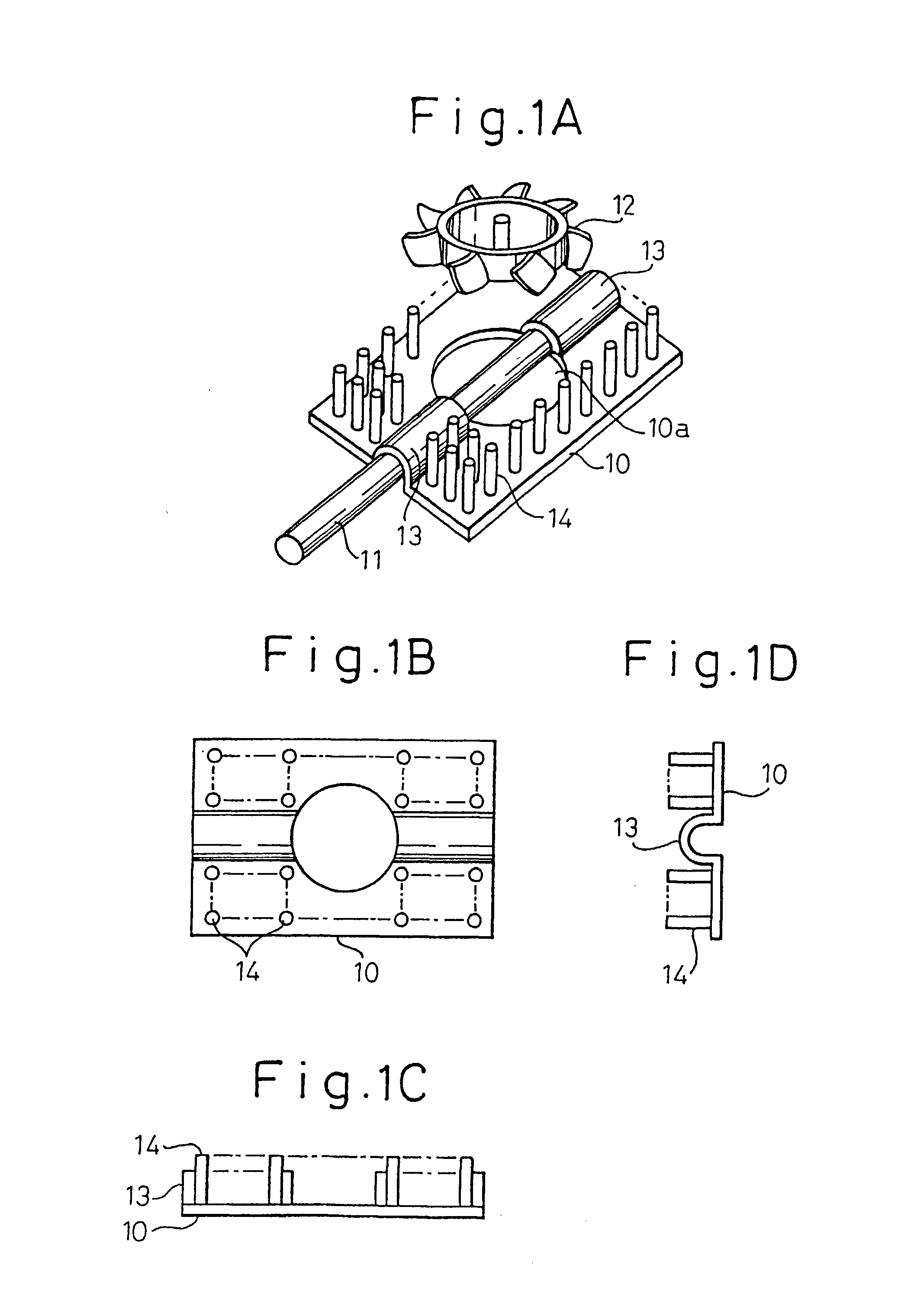
[0105]FIGS. 1A˜1D are views showing the present invention. FIG. 1A is a perspective view, FIG. 1B is an upper view, FIG. 1C is a front view, and FIG. 1D is a side view. In these figures, reference numeral 10 is a heat sink body, reference numeral 11 is a heat pipe corresponding to the heat transmitting member described in the scope of claim of the patent, and reference numeral 12 is a cooling fan. The heat sink body is formed into a rectangular plate shape. There is provided a cooling fan 12 above the heat sink body 10. The cooling fan 12 is embedded in a space 10a under the condition that a shaft of the cooling fan 12 is supported by a cover mounted on the heat sink body 10. There is provided a tunnel-shaped heat pipe accommodating section 13 into which a heat pipe 11 is inserted while the heat pipe 11 crosses two sides of the heat sink body 10 which are opposed to each other. This heat pipe accommodating section 13 corresponds to the holding section described in the scope of claim...

third embodiment

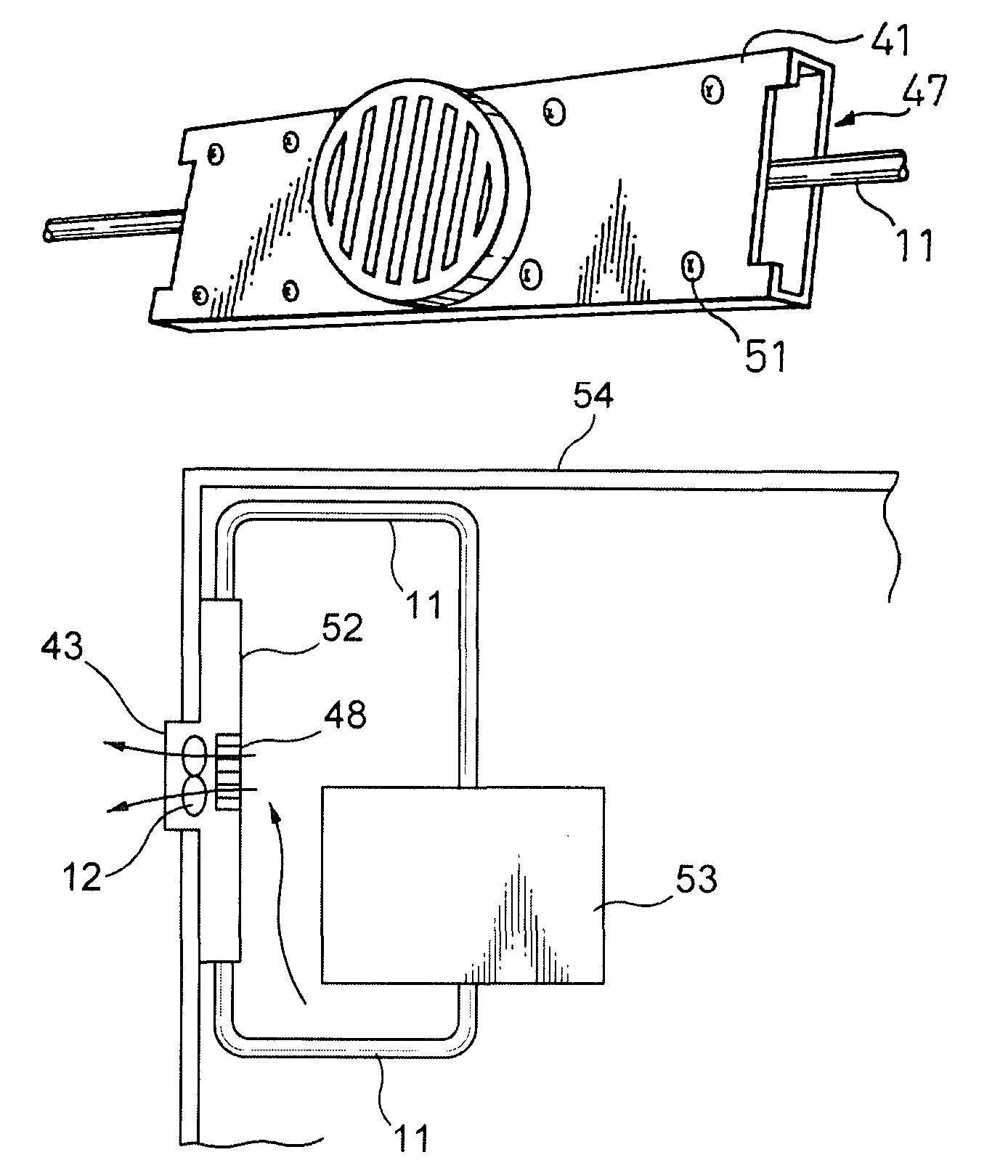
[0116]In the third embodiment, the printed board is also used as a cover to support the cooling fan 12. Therefore, it is possible to ignore a space in the cooling fan in which the printed board is conventionally arranged. Consequently, it is possible to reduce the thickness of the heat sink including the cooling fan.

[0117]When only the cooling fan 12 is supported on the printed board 18, which is also used as a cover, an empty space is generated. In order to utilize the empty space, a portion of the drive circuit, which is conventionally mounted in the fan motor, can be arranged on the upper surface of the printed board. When the fan motor drive circuit is arranged being separated into the fan motor and onto the printed board, the thickness of the cooling fan can be reduced. In this connection, this printed board is also used as an upper lid of the box 15 in which the heat sink body is accommodated.

[0118]FIG. 4 is a perspective view showing the fourth embodiment of the present inven...

seventh embodiment

[0122]FIG. 7 is a perspective view showing the present invention. In this embodiment, the box-shaped cover 31 is attached onto the printed board 18 in such a manner that the box-shaped cover 31 is laid upside down on the printed board 18. There is formed a long hole 34 on at least one side which is different from the side of the box 15 on which the slits 17 are formed. When the surface on which the slits 17 are formed and the surface on which the long hole 34 is formed are shifted from each other, it is possible to shift the suction side and the discharge side. Therefore, the cooling air can be prevented from going round.


PUM


Abstract

The present invention relates to a heat sink. More particularly, the present invention relates to a heat sink used for radiating heat from an integrated circuit package such as a micro-processor arranged in a portable type electronic apparatus such as a notebook type personal computer and also used for radiating heat from a hard disk unit used in an electronic apparatus. The heat sink comprises: a heat transmitting member for transmitting heat generated by a heating component; a holding section for holding the heat transmitting member; and a heat sink body having a space in which a cooling fan having at least blades and a drive motor is embedded, wherein a portion of the holding section for holding the heat transmitting member, the portion being located below the space, is cut out.

Description

[0001]This application is a DIVISION of prior application Ser. No. 09 / 820,980 filed Mar. 30, 2001 now U.S. Pat. No. 6,345,664 which is a DIVISION of a prior application Ser. No. 09 / 026,649 filed on Feb. 20, 1998 now U.S. Pat. No. 6,345,664.BACKGROUND OF THE INVENTION[0002]1. Field of the Invention[0003]The present invention relates to a heat sink. More particularly, the present invention relates to a heat sink used for diffusing heat generated by an integrated circuit package, in which heat is generated, such as a microprocessor unit incorporated into portable electronic equipment such as a notebook-type computer. Also, the present invention relates to a heat sink used for diffusing the heat generated by a hard disk device incorporated into portable electronic equipment.[0004]2. Description of the Related Art[0005]Recently, a microprocessor of high performance has been incorporated into a portable type electronic equipment for the purpose of increasing the processing speed and the p...

Claims


Application Information

Patent Timeline
Patent Type & Authority Patents(United States)
IPC IPC(8): H05K7/20H01L23/36F28D15/02H01L23/427H01L23/467
CPCF28D15/0266F28F1/12H01L23/427H01L23/467F28D15/0275H01L2924/0002H01L2924/00F28F13/06H05K7/20
Inventor KATSUI, TADASHI
Owner FUJITSU LTD
Why Eureka
Try Eureka