Sample carrier
a sample carrier and sample technology, applied in the field of sample carriers, can solve the problems of increased labor, time, and additional material costs, and the evaporation of aqueous or other solvent-containing sample liquids that are often subject to considerable evaporation, and achieve the effect of reducing labor costs, increasing material costs, and increasing the cost of materials
- Summary
- Abstract
- Description
- Claims
- Application Information
AI Technical Summary
Benefits of technology
Problems solved by technology
Method used
Image
Examples
first embodiment
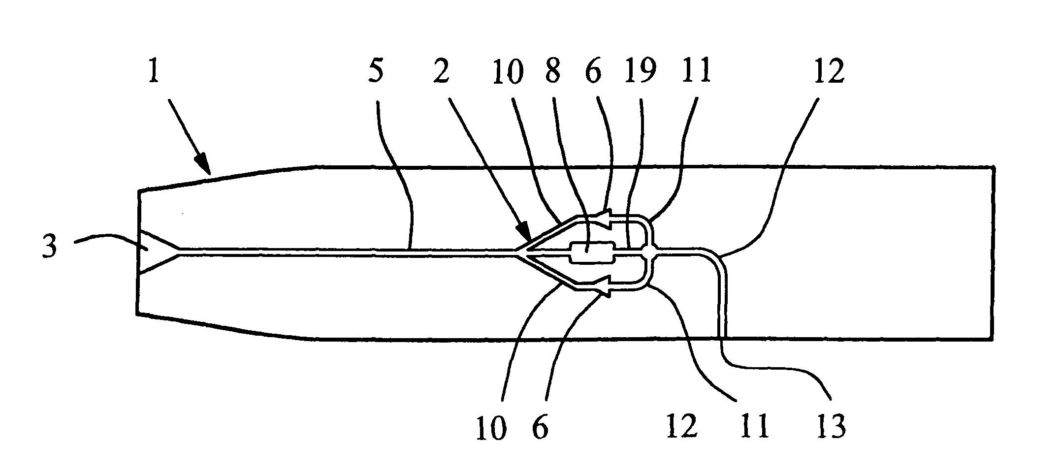
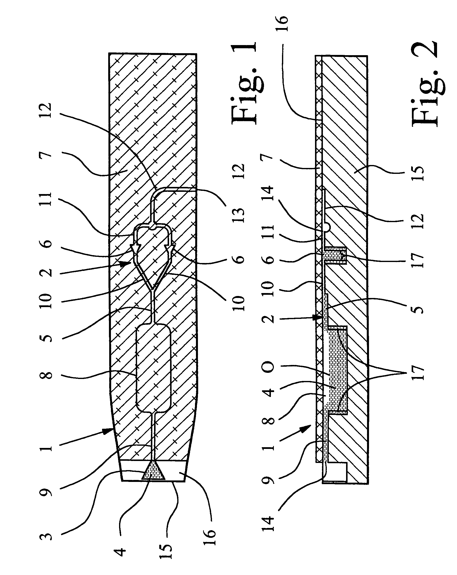
[0025]Preferably all the cavities 2 are formed in the base body 15 of the sample carrier 1. In particular, all cavities 2 are open proceeding from the flat side 16 of the base body 15 and toward the flat side 16, formed for example, by cups, riffles, grooves, recesses or the like. The covering 7 is cemented, laminated or in some other way, applied to the base body 15 and its flat side 16, and covers all cavities 2 of the sample carrier 1, except for the sample receiver 3 in the first embodiment, so that the cavities 2 are also closed to the top, as indicated in FIGS. 1 and 2. In the embodiment, the sample carrier 1 is thus made preferably in two parts. Alternatively, the sample carrier 1 can also be made in one part or can have several coverings 7 which can optionally be applied separately. Instead of the preferred film-like execution of the covering 7, it can also be formed, for example, by a glass plate or other suitable material with suitable properties with suitable shaping.
[002...
third embodiment
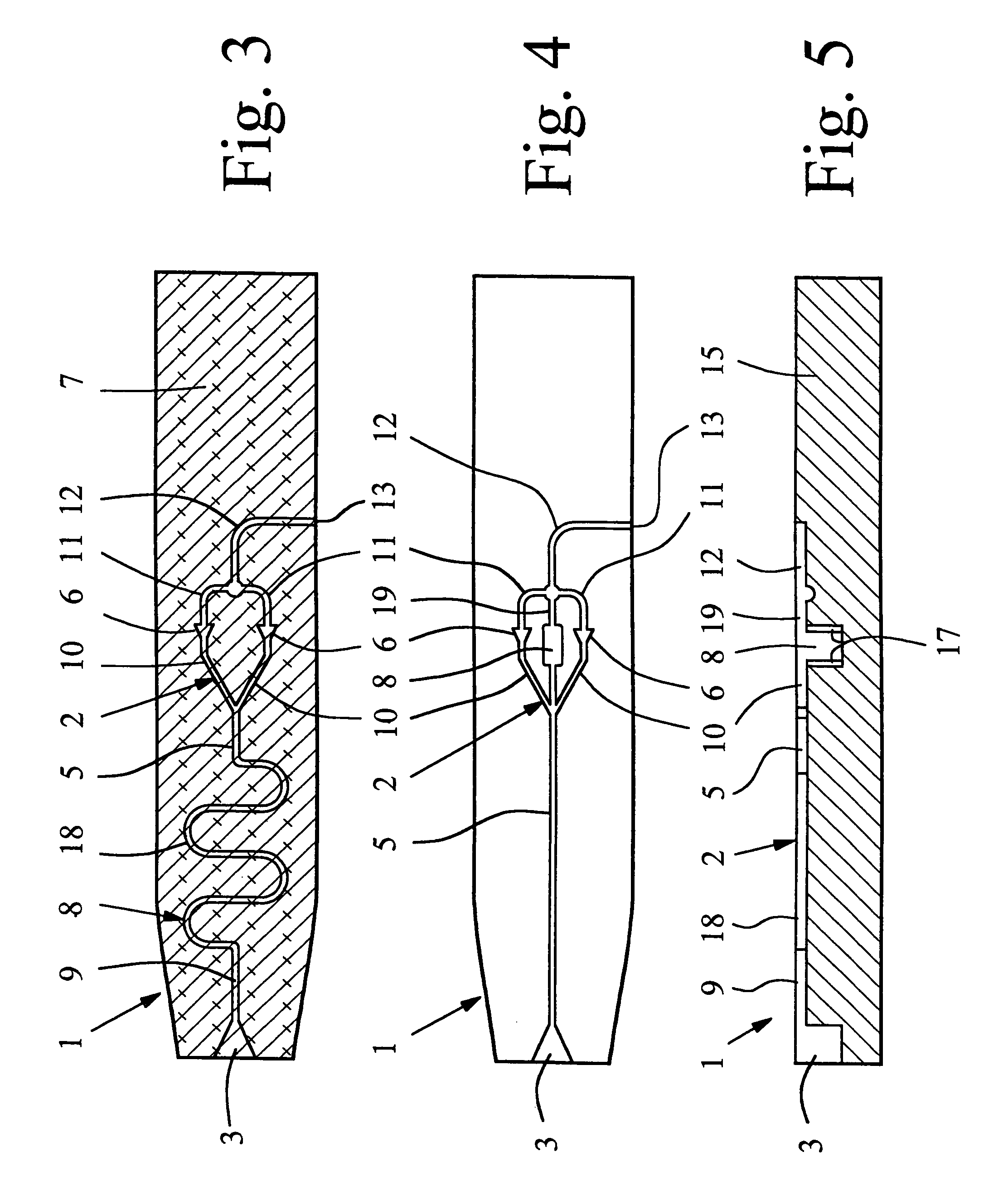
[0043]In FIGS. 4 and 5, the sample liquid 4 and the covering 7 are omitted for the sake of simplification, FIG. 4 showing an overhead view which corresponds to FIGS. 1 and 3. FIG. 4 shows the sample carrier 1. The reservoir 8 is connected to the distribution channel 5 parallel to the sample chambers 6. In particular, the reservoir 8, after or with the sample chambers 6 and their feed channels 10, is connected to the latter on the end of the distribution channel 5 so that the reservoir 8 can be filled with sample liquid 4 after the sample chambers 6, in order to first allow rapid filling of the sample chambers 6 with sample liquid 4.
[0044]In the third embodiment, the reservoir 8 is made preferably in the manner of a cup or chamber. In addition, the reservoir 8 is connected to the ventilation collecting channel 12 for ventilation and aeration via another connecting channel 19. Preferably between this other connecting channel 19 and the reservoir 8 or the ventilation collecting channel...
PUM
| Property | Measurement | Unit |
|---|---|---|
| holding volumes | aaaaa | aaaaa |
| relative atmospheric humidity | aaaaa | aaaaa |
| temperature | aaaaa | aaaaa |
Abstract
Description
Claims
Application Information
 - R&D
- Intellectual Property
- Life Sciences
- Materials
- Tech Scout
- Unparalleled Data Quality
- Higher Quality Content
- 60% Fewer Hallucinations
Browse by: Latest US Patents, China's latest patents, Technical Efficacy Thesaurus, Application Domain, Technology Topic, Popular Technical Reports.
© 2025 PatSnap. All rights reserved.Legal|Privacy policy|Modern Slavery Act Transparency Statement|Sitemap|About US| Contact US: help@patsnap.com


