Position measuring system for working machine

a technology for working machines and measuring systems, applied in the field of position measuring systems for working machines, can solve the problems of serious influence resulting from the change in the measurement accuracy of the machine-equipped gps, the change in the gps measurement accuracy, and the reduction of working efficiency, so as to achieve accurate measurement and increase the effect of working efficiency

Inactive Publication Date: 2010-11-09
NIHON KENKI CO LTD
View PDF21 Cites 25 Cited by
  • Summary
  • Abstract
  • Description
  • Claims
  • Application Information

AI Technical Summary

Benefits of technology

[0007]It is an object of the present invention to provide a position measuring system for a working machine, which can accurately measure the position of a monitoring point and can ensure high working efficiency even when measurement accuracy has changed.
[0011]Thus, by correcting the computation for the position of the monitoring point based on the yaw angle measured by the yaw angle measuring means when measurement accuracy of at least one of the at least two three-dimensional position measuring means lowers, the position of the monitoring point can be accurately measured and working efficiency can be increased even when the measurement accuracy has changed.

Problems solved by technology

However, the system disclosed in JP,A 2001-98585 has a problem of changes in GPS measurement accuracy.
If the measurement accuracy of the machine-equipped GPS changes as mentioned above, the measurement results enough to perform management cannot be obtained and the work must be suspended, thus leading to a problem of reduction in working efficiency.
In the system disclosed in JP,A 2001-98585, particularly, an influence resulting from change in the measurement accuracy of the machine-equipped GPS is serious because the bucket position is indirectly measured from the GPS measurement result.

Method used


Image

  • Position measuring system for working machine
  • Position measuring system for working machine
  • Position measuring system for working machine

Examples


Embodiment Construction

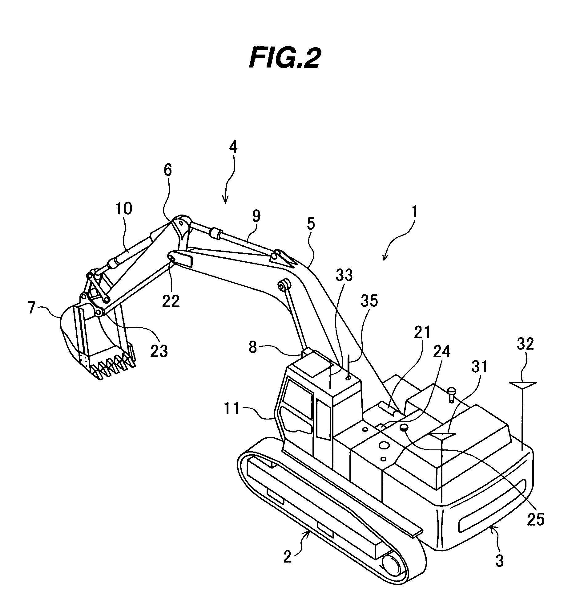
[0033]A position measuring system for a working machine according to an embodiment of the present invention will be described below with reference to FIGS. 1 to 11. In this embodiment, the present invention is applied to a crawler type hydraulic excavator, i.e., a construction machine as typical one of working machines, and a monitoring point is set to a bucket fore end of the hydraulic excavator.

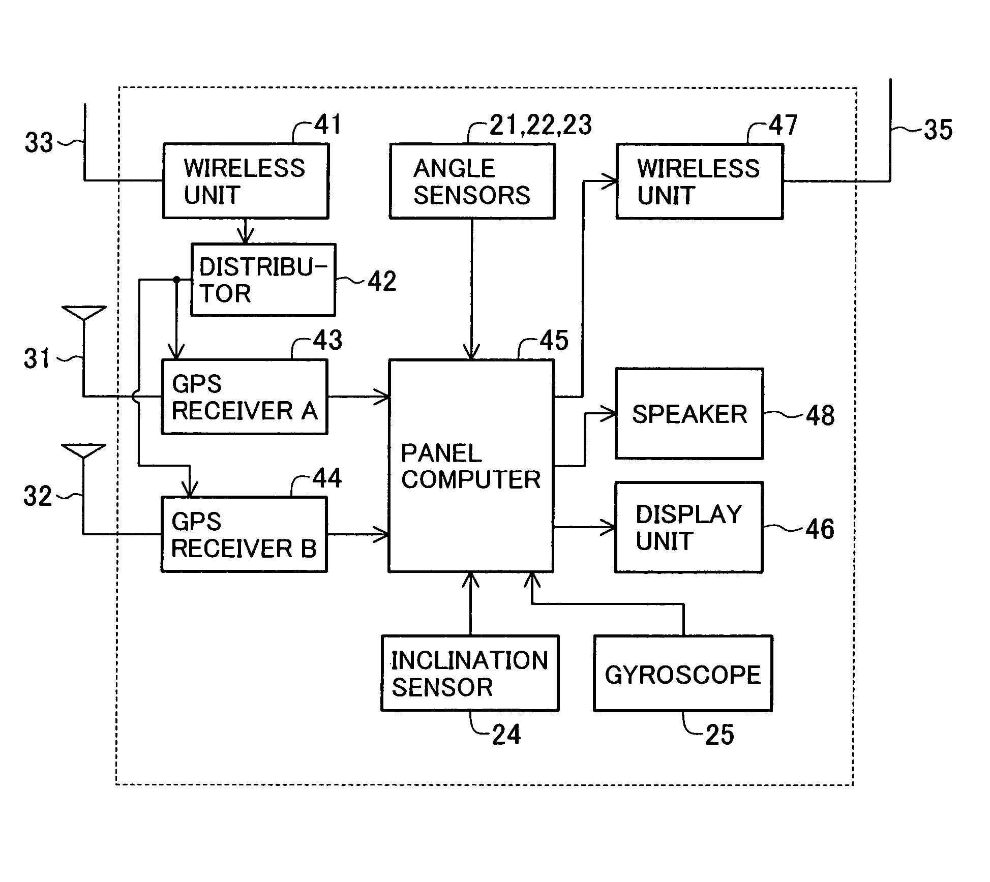
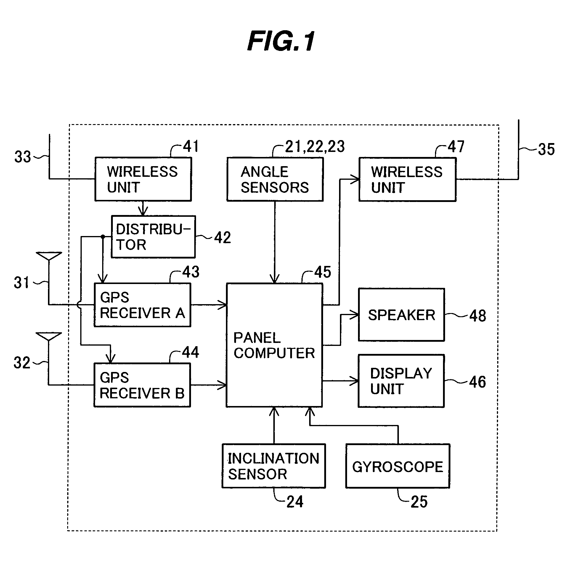
[0034]FIG. 1 is a block diagram showing the configuration of a position measuring system for a construction machine according to one embodiment of the present invention.

[0035]The position measuring system comprises a wireless unit 41 for receiving correction data (described later) from a reference station via an antenna 33; a distributor 42 for distributing the correction data received by the wireless unit 41; GPS receivers 43, 44 for measuring respective three-dimensional positions of GPS antennas 31, 32 in real time based on the correction data distributed from the distributor 42 and sign...


PUM


Abstract

The invention is intended to provide a position measuring system for a working machine, which can accurately measure the position of a monitoring point and can ensure high working efficiency even when measurement accuracy of a machine-equipped GPS has changed. A panel computer (45) computes the position of the monitoring point, which is set on an operating mechanism, in a three-dimensional space based on values measured by GPS receivers (43, 44) and angle sensors (21, 22, 23). When measurement accuracy of at least one of at least two GPS receivers lowers, the panel computer (45) corrects the computation for the position of the monitoring point based on a yaw angle measured by a gyroscope (25) for measuring the yaw angle of a machine body.

Description

TECHNICAL FIELD[0001]The present invention relates to a position measuring system for a working machine such as a hydraulic excavator, and more particularly to a position measuring system for a working machine, which is suitable for measuring an absolute position of a monitoring point in a three-dimensional space.BACKGROUND ART[0002]Recently, it has been practiced in construction sites to measure the position of a monitoring point set on a construction machine by employing a three-dimensional position measuring device, such as a GPS, for management of work. One typical example of the monitoring point is a position of an operating mechanism of the construction machine, for example, a bucket fore end position of a hydraulic excavator. By measuring the bucket fore end position, progress situations of work under execution can be confirmed by comparing measured data with preset landform data and target configuration data, and the management of the work can be performed during the executi...

Claims


Application Information

Patent Timeline
Patent Type & Authority Patents(United States)
IPC IPC(8): G06F19/00G01C15/00E02F9/20G01S5/14
CPCE02F9/2045G01S19/14G01S19/23G01S19/47G01S19/54
Inventor ISHIBASHI, HIDETOFUJISHIMA, KAZUO
Owner NIHON KENKI CO LTD
Why Eureka
Try Eureka