
Vehicle window security screen system

Inactive Publication Date: 2010-11-16
JOHNSTON LORNE G +1
View PDF74 Cites 16 Cited by
  • Summary
  • Abstract
  • Description
  • Claims
  • Application Information

AI Technical Summary

Benefits of technology

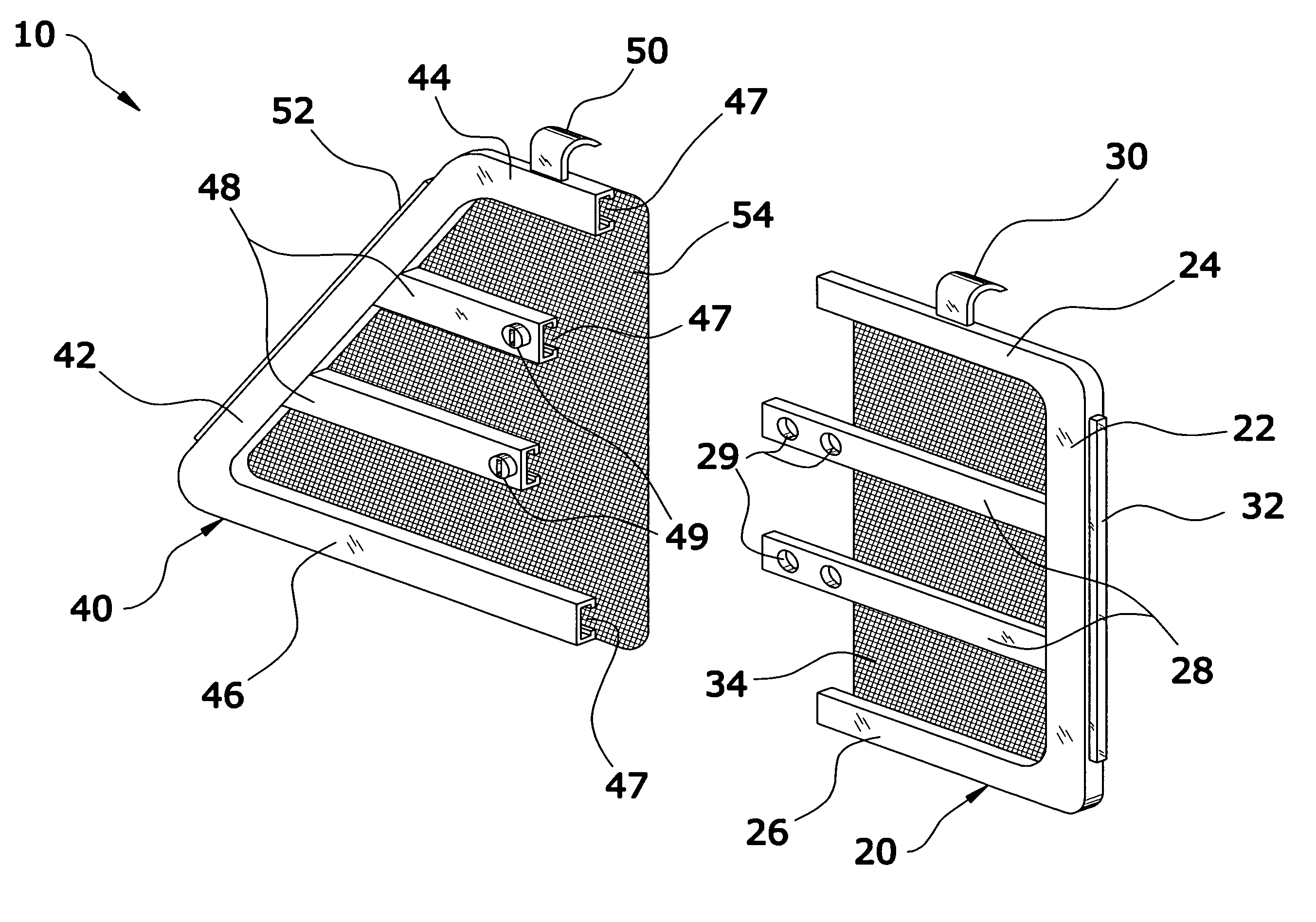
[0010]The general purpose of the present invention is to provide a vehicle window security screen system that has many of the advantages of the vehicle window screens mentioned heretofore. The invention generally relates to a vehicle window screen which includes a first frame having a first mesh and a second frame having a second mesh adjustably connected to one another. The first frame and the second frame form the shape of a window opening in a vehicle to secure the interior contents of a vehicle while simultaneously providing adequate ventilation.
[0015]An additional object is to provide a vehicle window security screen system that reduces the ability of another to gain unauthorized access to the interior of a vehicle.
[0016]A further object is to provide a vehicle window security screen system that decreases solar loading within a vehicle to prevent harm to a pet within the vehicle.
[0017]A further object is to provide a vehicle window security screen system that allows pet owners to keep their pets within a vehicle during hot days.
[0018]Another object is to provide a vehicle window security screen system that prevents the escape of a pet from a vehicle.
[0020]A further object is to provide a vehicle window security screen system that is easy and efficient to install.

Problems solved by technology

Vehicle owners with pets face a serious dilemma when traveling with pets: leave them in the car with the windows up which will increase the temperature of the interior to potentially deadly levels for the pet, remove the pet from the vehicle, or risk the security of their vehicle by opening their windows.
Opening the windows of a vehicle creates a security problem for the user as any unscrupulous individual could gain access through the upper slot created in the door.
Another problem is that opening the windows of the vehicle only slightly does not allow for adequate airflow through the vehicle on hot days resulting in an extremely hot temperature within the interior of the vehicle.
Various complex devices have been created to increase vehicle ventilation while parked (e.g. solar powered blowers, etc.) but these devices are expensive and difficult to use.

Method used


Image

  • Vehicle window security screen system
  • Vehicle window security screen system
  • Vehicle window security screen system

Examples


Embodiment Construction

A. Overview

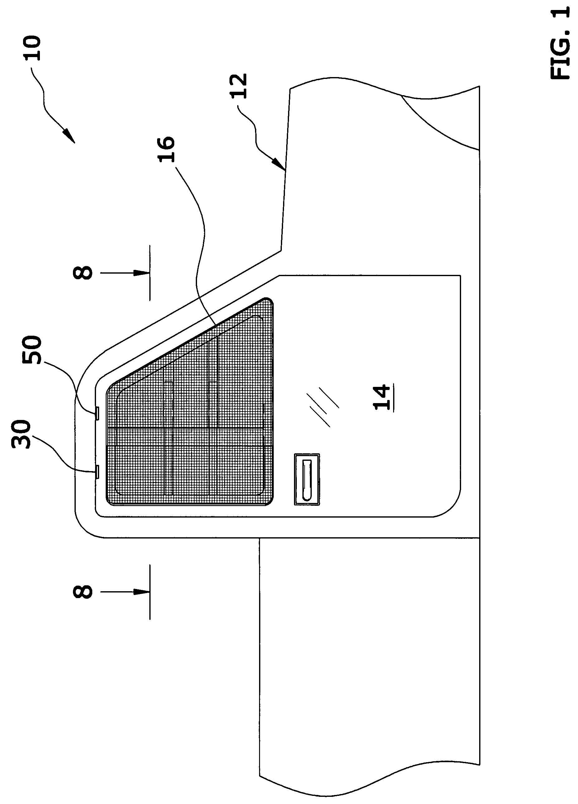
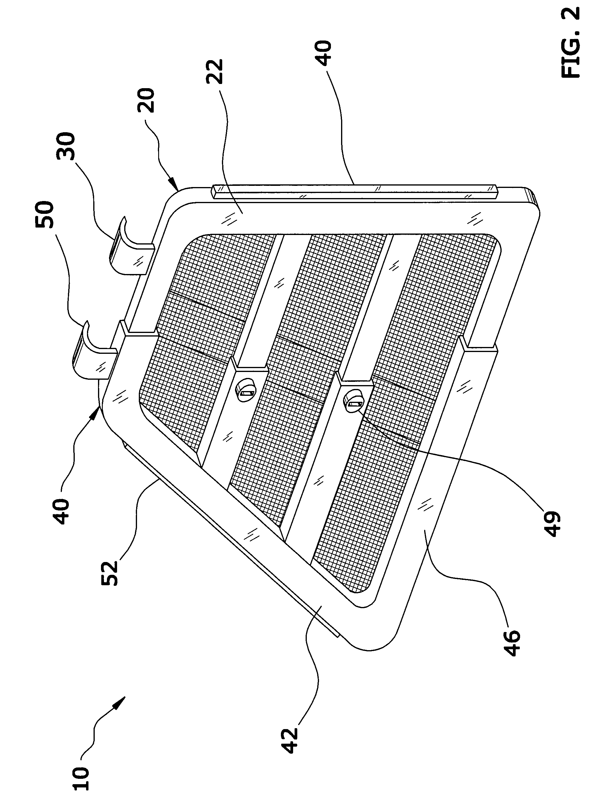
[0031]Turning now descriptively to the drawings, in which similar reference characters denote similar elements throughout the several views, FIGS. 1 through 8 illustrate a vehicle window security screen system 10, which comprises a first frame 20 having a first mesh and a second frame 40 having a second mesh adjustably connected to one another. The first frame 20 and the second frame 40 form the shape of a window opening 16 in a vehicle 12 to secure the interior contents of a vehicle 12 while simultaneously providing adequate ventilation. When the first frame 20 and the second frame 40 are assembled, they form the shape of the window opening 16 they are to be placed in (e.g. door 14 of a vehicle 12, building, camper, etc.). The frames 20, 40 may be constructed of various types of materials (e.g. metal, plastic) and may also be colored to correspond to the structure they are being attached to.

B. First Frame

[0032]FIG. 3 best illustrates the first frame 20. The first frame 2...


PUM


Abstract

A vehicle window security screen system for providing interior ventilation of a vehicle while maintaining the security of the vehicle. The vehicle window security screen system generally includes a first frame having a first mesh and a second frame having a second mesh adjustably connected to one another. The first frame and the second frame form the shape of a window opening in a vehicle to secure the interior contents of a vehicle while simultaneously providing adequate ventilation.

Description

CROSS REFERENCE TO RELATED APPLICATIONS[0001]I hereby claim benefit under Title 35, United States Code, Section 119(e) of U.S. provisional patent application Ser. No. 60 / 860,692 filed Nov. 24, 2006. The 60 / 860,692 application is hereby incorporated by reference into this application.STATEMENT REGARDING FEDERALLY SPONSORED RESEARCH OR DEVELOPMENT[0002]Not applicable to this application.BACKGROUND OF THE INVENTION[0003]1. Field of the Invention[0004]The present invention relates generally to vehicle window screens and more specifically it relates to a vehicle window security screen system for providing interior ventilation of a vehicle while maintaining the security of the vehicle.[0005]2. Description of the Related Art[0006]Any discussion of the related art throughout the specification should in no way be considered as an admission that such related art is widely known or forms part of common general knowledge in the field.[0007]Vehicle owners with pets face a serious dilemma when tr...

Claims


Application Information

Patent Timeline
IPC IPC(8): A47G5/00
CPCB60J1/20B60R21/12Y10S160/02
Inventor JOHNSTON, LORNE G.BAREHAM, MONA A.
Owner JOHNSTON LORNE G
Learn More