Expansion valve having a grooved valve member and refrigeration device including the same

a technology of expansion valve and grooved valve member, which is applied in the direction of lighting and heating apparatus, process and machine control, instruments, etc., can solve the problems of easy deformation, low mechanical strength of honeycomb pipe, low reliability of electric expansion valve, etc., and achieves the effect of reducing the noise generated by the refrigerant flow, facilitating formation, and effectively reducing the noise of the refrigerant flow

Inactive Publication Date: 2010-11-16
DAIKIN IND LTD
View PDF14 Cites 29 Cited by
  • Summary
  • Abstract
  • Description
  • Claims
  • Application Information

AI Technical Summary

Benefits of technology

[0011]However, the conventional method A has a problem in that the extremely narrow passages are easily clogged with foreign matter. Further, the porous member, the honeycomb pipe, the capillaries, and the molecular sieve, which all have low mechanical strength, deform easily. This lowers the reliability of the electric expansion valve.

Problems solved by technology

However, the conventional method A has a problem in that the extremely narrow passages are easily clogged with foreign matter.
Further, the porous member, the honeycomb pipe, the capillaries, and the molecular sieve, which all have low mechanical strength, deform easily.
This lowers the reliability of the electric expansion valve.
The conventional method B has a problem in that the ejection velocity of the vaporized refrigerant flowing through the throttle cannot be kept constant.
Further, bubbles in the refrigerant cannot be broken up and uniformly dispersed.
For these reasons, noise generated by the refrigerant flow cannot be sufficiently reduced.
Thus, the effect for reducing noise is not sufficient.
Further, it is difficult to fully close the two throttles at the same time.
Thus, there is a problem in that an intermediate pressure between the two throttles cannot be generated and maintained when fully closing the throttles.
Thus, the flow amount of the refrigerant cannot be accurately controlled.
If the cross-sectional area of each refrigerant flow passage forming the throttle is reduced to solve this problem, the refrigerant flow passages may easily clog with or catch foreign matter.

Method used


Image

  • Expansion valve having a grooved valve member and refrigeration device including the same
  • Expansion valve having a grooved valve member and refrigeration device including the same
  • Expansion valve having a grooved valve member and refrigeration device including the same

Examples


first embodiment

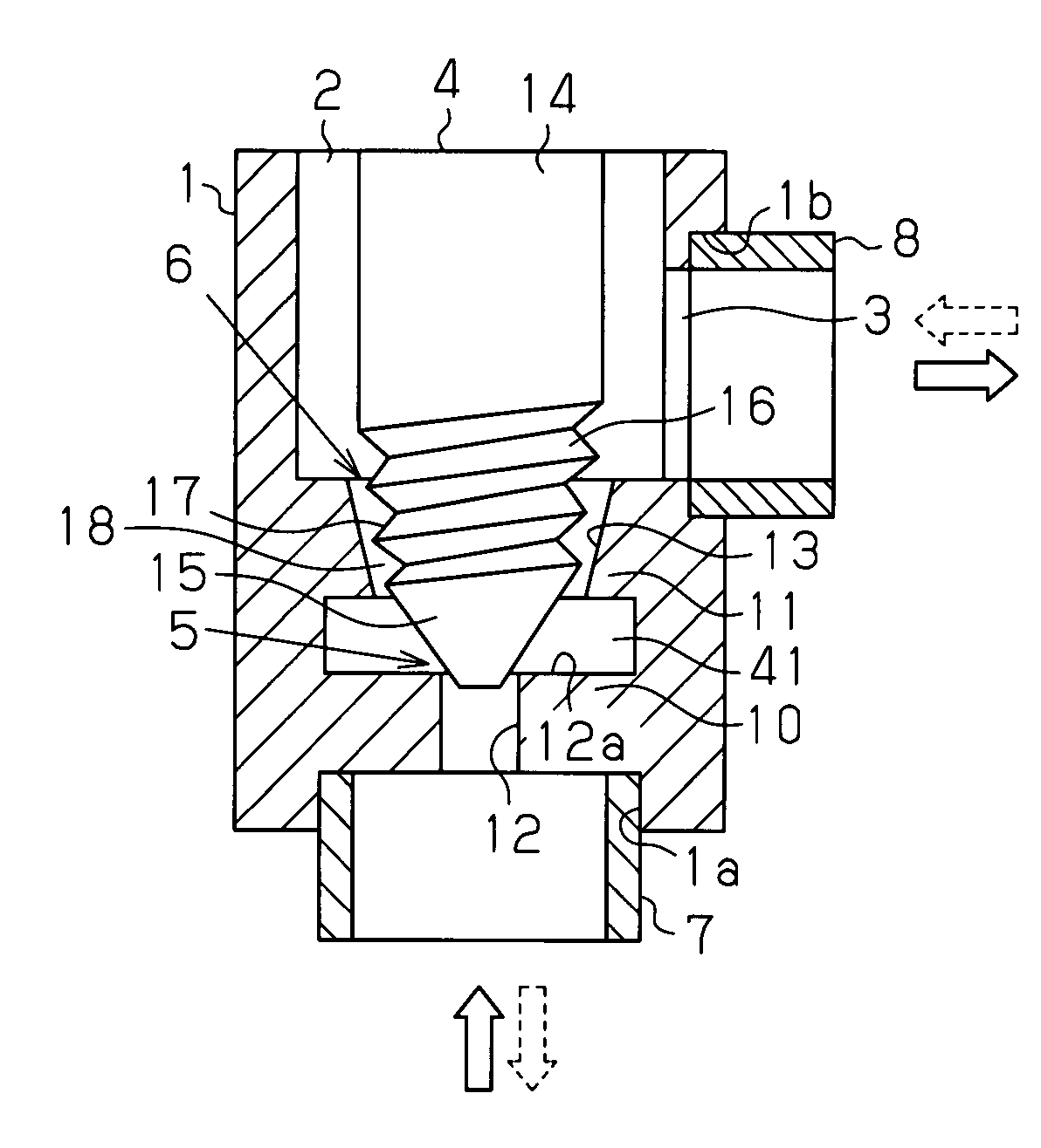
[0093]An expansion valve according to a first embodiment of the present invention will now be described with reference to FIG. 1.

[0094]As shown in FIG. 1, the expansion valve includes a valve body 1, in which an inlet port 1a and an outlet port 1b are formed. The valve body 1, which is substantially cylindrical, and includes a valve chamber 2 and a refrigerant flow passage 3 formed in the valve body 1. In the valve body 1, the valve chamber 2 and the refrigerant flow passage 3 communicate the inlet port 1a with the outlet port 1b. A valve member 4 is accommodated in the valve chamber 2. A first throttle 5 is arranged in the refrigerant flow passage 3 at an upstream side. A second throttle 6 is arranged in the refrigerant flow passage at a downstream side. A liquid tube 7 connecting an outdoor coil and the expansion valve is connected to the inlet port 1a. A pipe 8 connecting the expansion valve and an indoor coil is connected to the outlet port 1b. In the present embodiment, the inl...

second embodiment

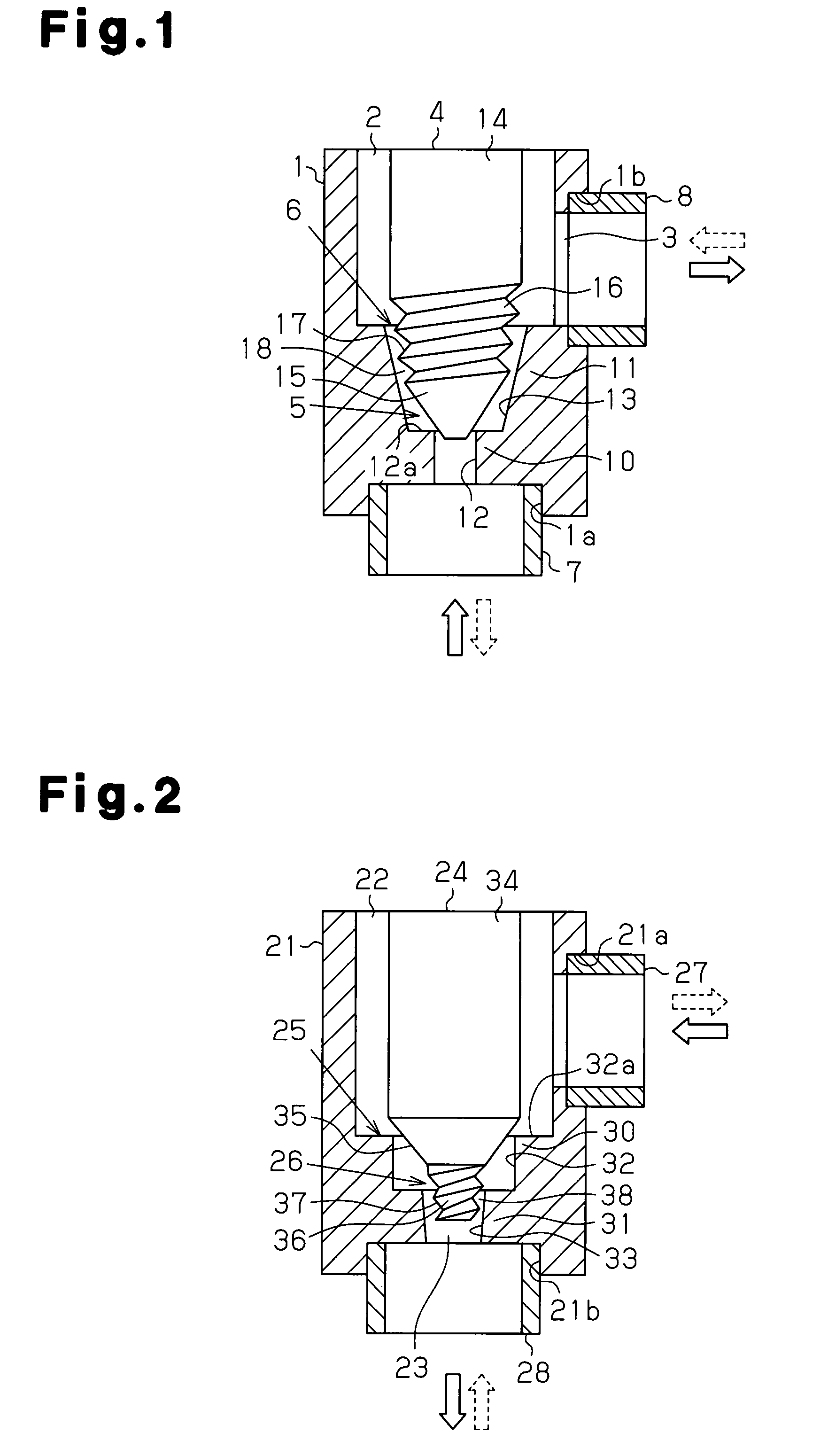
[0107]A second embodiment of the present invention will now be described with reference to FIG. 2. In an expansion valve of the second embodiment, refrigerant flows in a direction opposite to the direction of the refrigerant flow in the first embodiment.

[0108]As shown in FIG. 2, the expansion valve includes a valve body 21, in which an inlet port 21a and an outlet port 21b are formed. The valve body 21, which is substantially cylindrical, and has a valve chamber 22 and a refrigerant flow passage 23 formed inside the valve body 21. In the valve body 21, the valve chamber 22 and the refrigerant flow passage 23 communicate the inlet port 21a with the outlet port 21b. A valve member 24 is accommodated in the valve chamber 22. A first throttle 25 is arranged in the refrigerant flow passage 23 at an upstream side. A second throttle 26 is arranged in the refrigerant flow passage 23 at a downstream side. A liquid tube 27 connecting an outdoor coil and the expansion valve is connected to the...

third embodiment

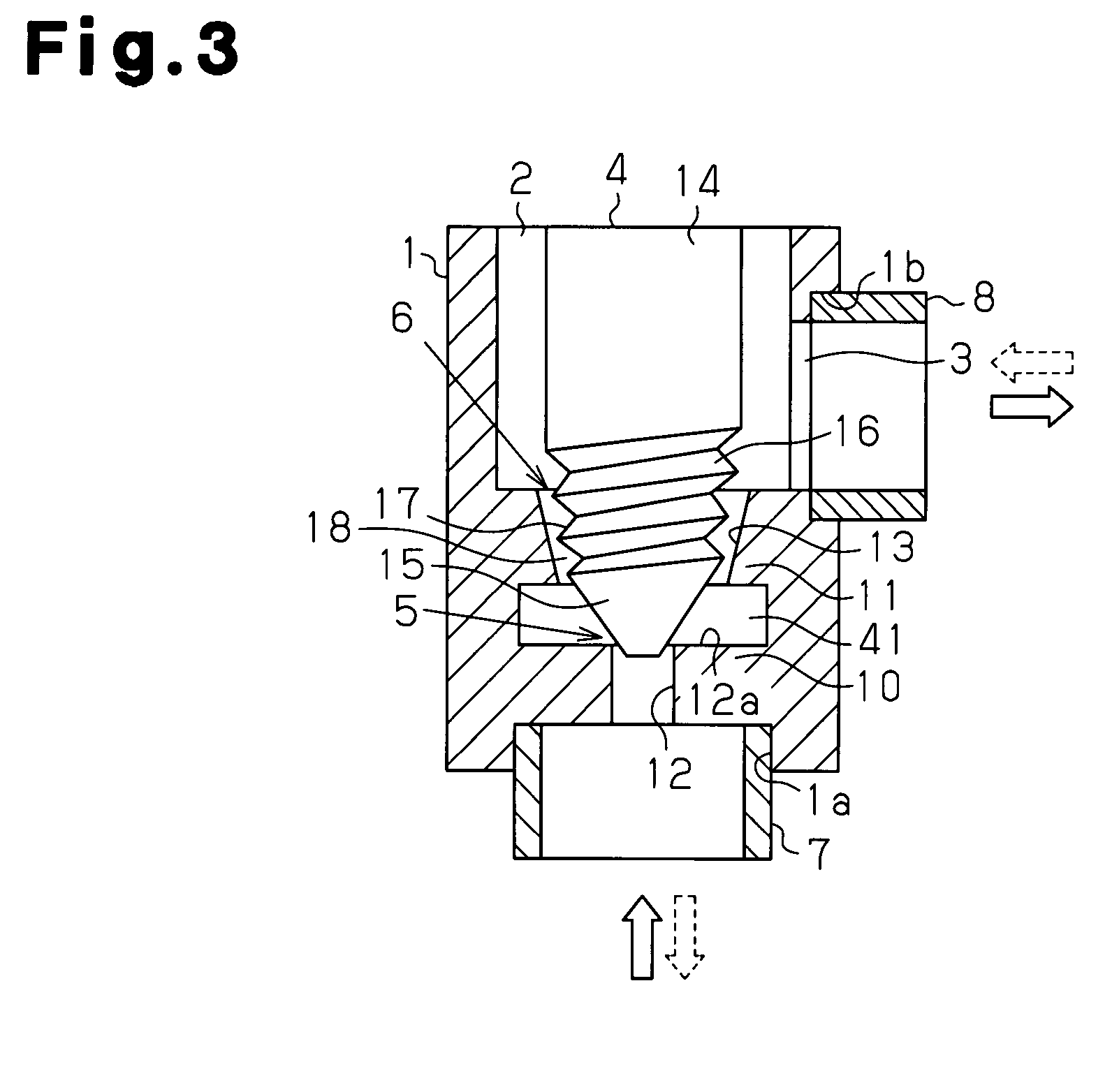
[0120]An expansion valve according to a third embodiment of the present invention will now be described with reference to FIG. 3. The components of the expansion valve of the third embodiment that are the same as the components in the first embodiment are given the same reference numerals as those components and will not be described in detail.

[0121]As shown in FIG. 3, a refrigerant flow passage 3 includes an enlarged space portion 41 formed between a first valve hole 12 and a second throttle 6. The enlarged space portion 41 is formed by increasing the inner diameter of part of the refrigerant flow passage 3. With this structure, the flow of refrigerant that has passed through a first throttle 5 generates a vortex in the enlarged space portion 41. The vortex effectively reduces the kinetic energy of the refrigerant flow. This structure further reduces the velocity fluctuations and the pressure fluctuations of the refrigerant flow and further reduces noise generated by the refrigeran...


PUM


Abstract

An expansion valve includes a valve body 1. The valve body 1 includes a first throttle 5 and a second throttle 6 arranged downstream from the first throttle 5. The second throttle 6 includes an outer surface of the second valve portion 16 and an inner surface of the second valve hole 13. A helical groove or a linear groove is formed in the outer surface of the second valve portion 16 or the inner surface of the second valve hole 13. Further, at least either one of the outer surface of the second valve portion 16 and the inner surface of the second valve hole 13 is tapered toward a distal end of a valve member 4.

Description

FIELD OF THE INVENTION[0001]The present invention relates to an expansion valve and a refrigeration device.BACKGROUND OF THE INVENTION[0002]A separate-type air conditioner conventionally includes a refrigeration circuit shown for example in FIG. 23. The refrigeration circuit includes a compressor 201, an outdoor coil 202, an expansion valve 203, and an indoor coil 204. The compressor 201 and the outdoor coil 202 are accommodated in an outdoor unit 205. The expansion valve 203 and the indoor coil 204 are accommodated in an indoor unit 206. An electric expansion valve, such as that shown in FIG. 24, is used as the expansion valve 203.[0003]The electric expansion valve includes a valve body 210, in which an inlet port 211 and an outlet port 212 are formed. A valve chamber 213 and a refrigerant flow passage 214 are formed in the valve body 210. The valve chamber 213 and the refrigerant flow passage 214 communicate the inlet port 211 with the outlet port 212. The valve body 210 has a par...

Claims


Application Information

Patent Timeline
Patent Type & Authority Patents(United States)
IPC IPC(8): F25B41/04F25B41/06G05D23/12F16K47/00F16L55/02
CPCF16K47/04F16K47/06F16K47/12F25B41/062F25B2341/0662F25B2500/01F25B2500/12F25B41/39F25B41/35F25B41/38Y02B30/70
Inventor YUKIMOTO, TOORU
Owner DAIKIN IND LTD
Why Eureka
Try Eureka