
Multiple nozzle evaporator for vacuum thermal evaporation

a technology of evaporator and vacuum thermal evaporation, which is applied in vacuum evaporation coating, chemical vapor deposition coating, coating, etc., can solve the problems of reducing unable to obtain large-area uniform thin films, and easy condensation of evaporated materials at the spouting portion, so as to improve the efficiency of use of a material to be evaporated

Active Publication Date: 2010-11-16
YAS
View PDF5 Cites 7 Cited by
  • Summary
  • Abstract
  • Description
  • Claims
  • Application Information

AI Technical Summary

Benefits of technology

The multiple nozzle evaporator achieves uniform thin film deposition on large-area substrates with improved material efficiency and reduced condensation, enhancing the overall thermal evaporation process by directing evaporated material to peripheral areas and optimizing heating distribution.

Problems solved by technology

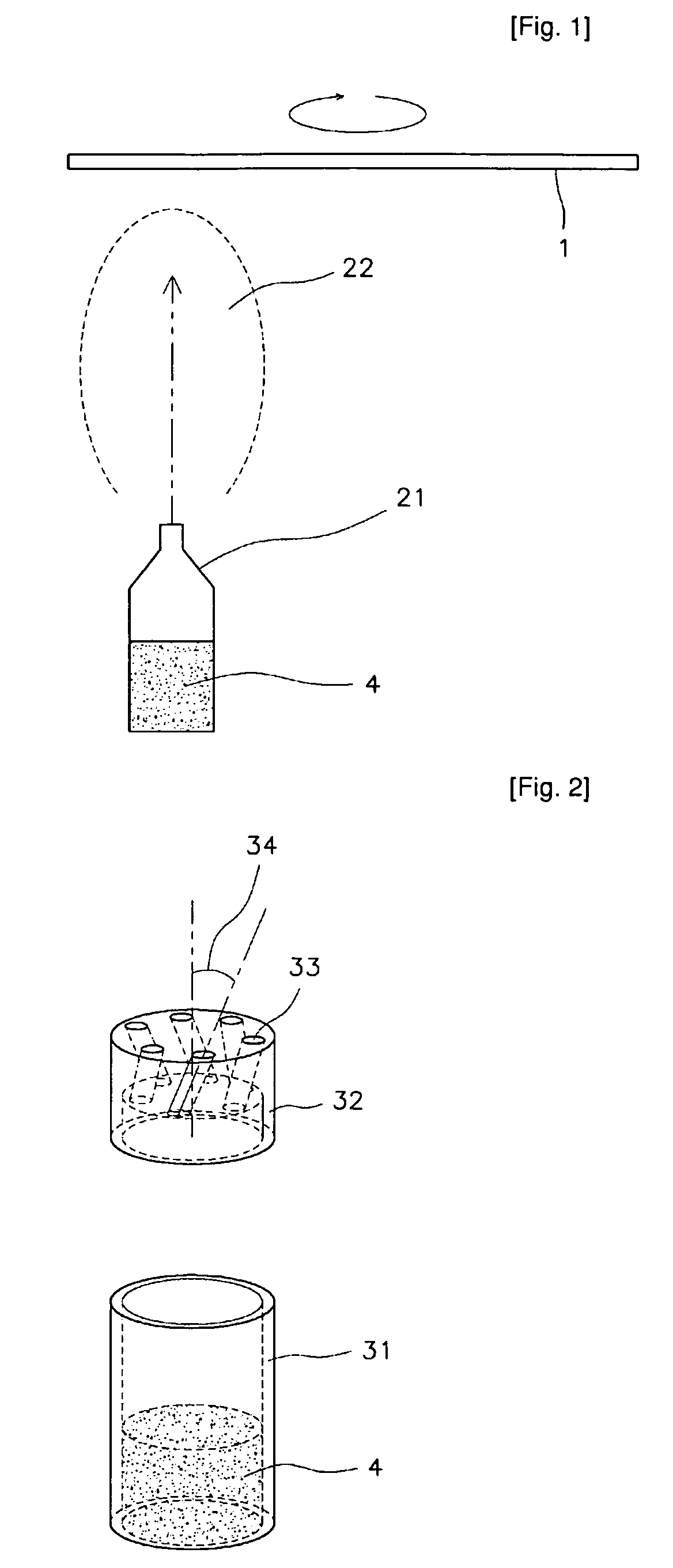
However, since the point evaporator causes most of the evaporated material to spout therefrom in a direction 22 directed by the spouting portion, it has a problem in that a large-area uniform thin film cannot be obtained.
However, this evaporation method has further problems in that the addition of an apparatus for rotating the substrate makes the evaporation system complicated and causes defects in final products, and the efficiency of use of a material is lowered.
Moreover, since the spouting portion is located at a center that is far away from a lateral heated portion in the conventional point evaporator, there is a disadvantage in that the evaporated material may be easily condensed at the spouting portion.
In case of the conical nozzle, it is difficult to achieve a desired spouting distribution, to process the nozzle and to grind the inside of the nozzle.
Furthermore, since an evaporation tube is located at the center of the nozzle, there is a disadvantage in that an evaporated material is condensed inside the evaporation tube in the same manner as the conventional point evaporator.

Method used


Image

  • Multiple nozzle evaporator for vacuum thermal evaporation
  • Multiple nozzle evaporator for vacuum thermal evaporation
  • Multiple nozzle evaporator for vacuum thermal evaporation

Examples


first embodiment

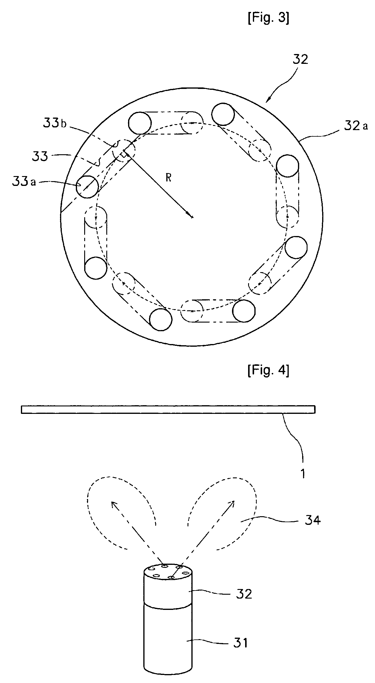
[0029]To perform vacuum thermal evaporation on a substrate 1 using the present invention, the multiple nozzle evaporator of the present invention is placed below a center of the substrate 1, as shown in FIG. 4. Then, the evaporator is heated so that a material to be evaporated is evaporated and spouts through the inclined evaporation tubes 33 toward lateral sides of the substrate and is finally deposited on the substrate.

[0030]When vacuum thermal evaporation is performed using the multiple nozzle evaporator for vacuum thermal evaporation according to the present invention, the evaporated material spouts toward the peripheral areas of the substrate by means of the evaporation tubes inclined to be directed to the peripheral areas, resulting in a thin film with a uniform thickness even in case of a large-area substrate. Since the evaporator is placed below the center of the substrate, it is possible to minimize the amount of the material to be wasted by being directed to the outside of...

second embodiment

[0034]FIG. 5 shows a perspective view of the present invention.

[0035]In this embodiment, a hollow portion 35 is formed along central portions of the nozzle unit 32 and the crucible 31, so that a central heater can be additionally installed in the hollow portion. The central heater enhances the heating capacity of the evaporator and also mainly heats the nozzle unit to prevent the evaporated material from being condensed within the evaporation tubes.

third embodiment

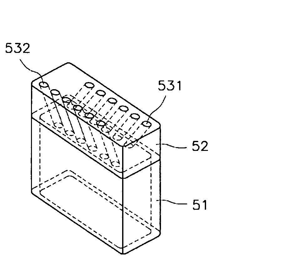
[0036]Referring to FIGS. 6 to 8, a multiple nozzle evaporator according to the present invention includes a rectangular crucible 51 and a rectangular nozzle unit 52. The crucible 51 is formed of a rectangular container that has an open top face and can receive a material to be evaporated therein. A coupling means for use in coupling with the nozzle unit is formed at an upper portion of the crucible.

[0037]The coupling means for coupling the nozzle unit with the crucible may be constructed of snap-fit protrusions provided at peripheries of the crucible and the nozzle unit where they are coupled with each other. Alternatively, the coupling means may be constructed of clamps or the like provided respectively at the crucible and the nozzle unit.

[0038]The nozzle unit 52 is formed with a plurality of evaporation tubes 531 and 532 extending from a top face to a bottom face of the nozzle unit. In particular, as a technical feature of this embodiment, the evaporation tubes are inclined in opp...


PUM


Abstract

Disclosed is a multiple nozzle evaporator in which a material to be evaporated in the evaporator can be deposited on a substrate with an improved efficiency of use of the material, thereby forming a large-area uniform thin film. The evaporator includes a cylindrical or rectangular post-shaped crucible 31 or 51 with an open top face; and a nozzle unit 32 having a body portion having a cylindrical or rectangular post-like shape with a height smaller than that of the crucible 31 or 51 and assembled to an upper portion of the crucible, and a plurality of evaporation tubes formed at an angle while penetrating through the body portion between top and bottom faces of the body portion. An evaporated material spouts toward peripheral areas of a substrate due to the inclined evaporation tubes, thereby improving the uniformity of a thin film to be deposited and the efficiency of use of the evaporated material, and preventing condensation of the evaporated material at a spouting portion.

Description

TECHNICAL FIELD[0001]The present invention relates to an evaporator for vacuum thermal evaporation, and more particularly, to a multiple nozzle evaporator in which a material to be evaporated in the evaporator can be deposited on a substrate with an improved efficiency of use of the material, thereby forming a large-area uniform thin film.BACKGROUND ART[0002]Generally, various thin-film forming techniques are used to fabricate semiconductor devices or flat panel display devices. One of them is a vacuum thermal evaporation method. The vacuum thermal evaporation method is a method of forming a thin film by placing a substrate at an upper side within a vacuum container, and heating an evaporator, which is placed below the substrate and contains a material to be evaporated, so that the evaporated material can be deposited on the substrate.[0003]FIG. 1 shows a point evaporator that is most popularly used in the vacuum thermal evaporation method. As shown in FIG. 1, the point evaporator 2...

Claims


Application Information

Patent Timeline
Patent Type & Authority Patents(United States)
IPC IPC(8): C23C16/00
CPCC23C14/243
Inventor KIM, SEONG-MOONJEONG, KWANG-HOCHOI, MYUNG-WOONPARK, HYUNG-WON
Owner YAS
Learn More