Multi-layer sliding member, and method for forming coating layer of sliding member

a sliding member and multi-layer technology, applied in the direction of crankshafts, mechanical equipment, transportation and packaging, etc., can solve the problems of low heat conduction, seizure, and worsening the adhesion of solid lubricant particles,

Active Publication Date: 2010-11-16
DAIDO METAL CO LTD
View PDF9 Cites 10 Cited by
  • Summary
  • Abstract
  • Description
  • Claims
  • Application Information

AI Technical Summary

Problems solved by technology

However, because the one formed by coating uses a resin binder, the heat conductivity of the coating layer is low and the frictional heat generated by the slide of the counter member is hard to escape to the housing side, resulting in a low heat conduction.
This causes a problem that seizure is likely to occur especially under starved lubricant conditions.
If attempting to maintain a soft surface state of the base material, the collision velocity of solid lubricant particles needs to be reduced, which would however worsen the adherability of the solid lubricant particles, and as a result, a required thickness is not obtained and a sufficient anti-seizure property cannot be obtained.
As described above, conventionally, when reforming the surface of the base material of a sliding member by means of a solid lubricant, a poor thermal conductive resin binder is used or a strain hardening of the surface of the base material is involved, which is problematic since it is difficult to obtain a sufficient anti-seizure property.

Method used


Image

  • Multi-layer sliding member, and method for forming coating layer of sliding member
  • Multi-layer sliding member, and method for forming coating layer of sliding member
  • Multi-layer sliding member, and method for forming coating layer of sliding member

Examples


Embodiment Construction

[0053]The present invention is explained below in detail with reference to the accompanied drawings.

1. Sliding Member According to the Present Invention

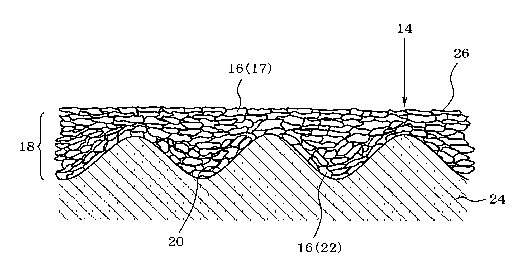
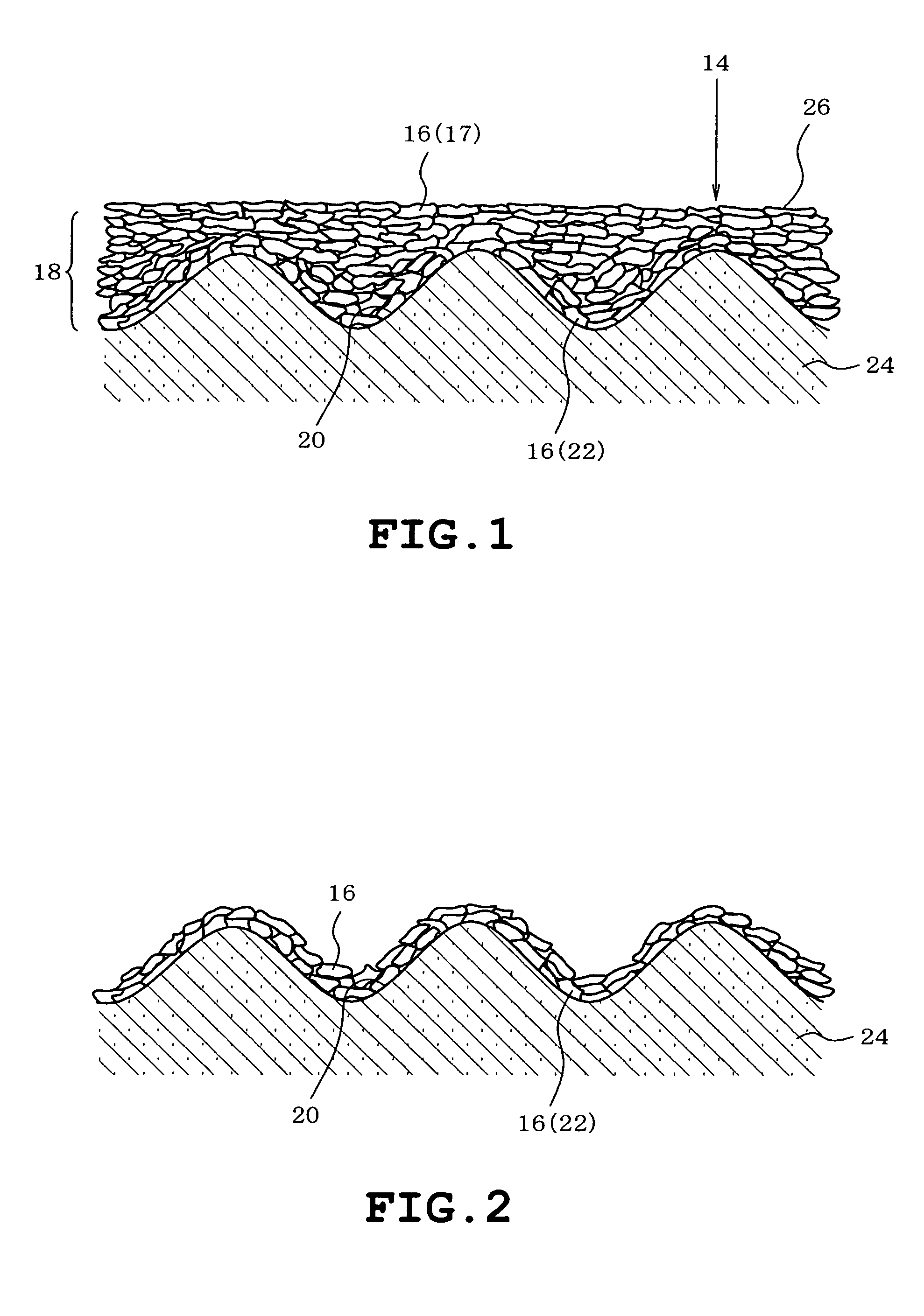
[0054]The present invention is targeted for a sliding member having a structure in which a coating layer with a sliding surface is adhered to the surface of a base material.

[0055]Although FIG. 8 shows a sliding member (slide bearing) 1 used for a radial bearing by way of example, this sliding member 1 used for a radial bearing is formed semi-cylindrically or cylindrically (not shown). As the structure before forming a coating layer of this sliding member used for a radial bearing, as illustrate in FIG. 9, the one with a bilayer structure in which a bearing alloy layer 3 is formed on a back metal layer 2, and the one with a multilayer structure in which an overlay layer is further formed in the surface of the bearing alloy layer 3 of FIG. 9 are often used, however, the one with one layer structure of only a bearing alloy layer may be ...


PUM

PropertyMeasurementUnit
surface sliding velocityaaaaaaaaaa
thicknessaaaaaaaaaa
pressureaaaaaaaaaa

Abstract

The present invention is intended to provide a sliding member which exhibits an excellent anti-seizure property even under starved lubricant conditions. In the present invention, there is provided a sliding member with a structure, in which a coating layer having a sliding surface is adhered to the surface of the base material, wherein the coating layer does not contain a resin binder but has solid lubricant plate crystal particles laminated therein, wherein these solid lubricant plate crystal particles have a lamellar crystal structure in which (001) planes are stacked in parallel, and at least in the sliding surface, the orientation index of the (001) plane of the solid lubricant plate crystal particles is 90% or more.

Description

BACKGROUND OF THE INVENTION[0001]The present invention relates to a sliding member formed by adhering a coating layer composed of solid lubricant plate crystal particles to the surface of a base material, and a method for forming the coating layer.[0002]In the slide bearing (sliding member) of an automotive engine, generally, an aluminum-base bearing alloy and a copper-base bearing alloy are used as the sliding layer. In recent years, while advances have been made which permit higher output power and higher rotational speed in automotive engines, the demand for improvement of fuel efficiency is high, and there is therefore a need for a low friction characteristic in the slide bearing. In particular, in vehicles, like a hybrid car, where frequent starting and stopping of an engine are repeated, a low friction characteristic under boundary lubricant conditions is required.[0003]In order to address the demand for a low friction characteristic under boundary lubricant conditions, reform...

Claims


Application Information

Patent Timeline
Patent Type & Authority Patents(United States)
IPC IPC(8): B32B1/00C10M169/00B32B3/00B32B5/16F16C19/00B05D3/00B05D1/12C01G39/06C10M111/04C10M169/04
CPCC23C24/06C23C26/00F16C33/043F16C33/14F16C33/16F16C33/201Y10S384/907Y10T428/25Y10T428/24628Y10T428/256Y10T428/24479Y10S384/91F16C33/1095F16C2223/32F16C2223/80
Inventor FUJITA, MASAHITOTSUJI, HIDEOOCHI, SHINJIIZUMIDA, MANABU
Owner DAIDO METAL CO LTD
Why Eureka
Try Eureka