Method and apparatus for controlling vehicle battery charging

a technology for charging vehicles and battery chargers, applied in the direction of secondary cell servicing/maintenance, electrochemical generators, transportation and packaging, etc., can solve the problems of battery life decline, battery charging units not operating at optimal efficiency, and battery life reduction, so as to maximize fuel economy, maximize energy efficiency of hybrid systems, and minimize fuel consumption

Active Publication Date: 2010-11-16
GM GLOBAL TECH OPERATIONS LLC
View PDF10 Cites 15 Cited by
  • Summary
  • Abstract
  • Description
  • Claims
  • Application Information

AI Technical Summary

Benefits of technology

[0007]What is disclosed is an electrical charging strategy and system for a high voltage electrical energy storage system able to supply electrical energy to a hybrid vehicle. The electrical charging strategy and system charges the electrical energy storage system to ensure that a state-of-charge of the electrical energy storage system at the end of a trip or driving cycle is substantially the same as the state-of-charge at the beginning of the trip. The electrical charging strategy and system preferably employs opportunity charging to achieve maximum energy efficiency of the hybrid system, thus minimizing fuel consumption and maximizing fuel economy.

Problems solved by technology

Over-depletion of battery SOC typically decreases battery life, whereas overcharging of the battery unnecessarily expends fuel, thus decreasing effective fuel economy of the vehicle.
At light motor-generator unit (MGU) loads, the battery charging unit is not operating at optimal efficiency, thus needlessly expending energy.
Furthermore, opportunities to more completely charge the battery are missed at higher engine efficiencies, due to current-limiting characteristics of the zero-current system.

Method used


Image

  • Method and apparatus for controlling vehicle battery charging
  • Method and apparatus for controlling vehicle battery charging
  • Method and apparatus for controlling vehicle battery charging

Examples


Embodiment Construction

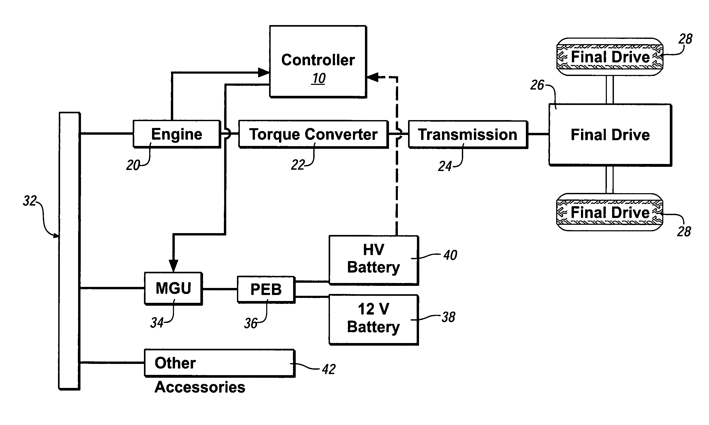
[0024]Referring now to the drawings, wherein the showings are for the purpose of illustrating the invention only and not for the purpose of limiting the same, FIG. 1 shows a schematic drawing of a vehicle propulsion system including an exemplary internal combustion engine and control system which has been constructed in accordance with an embodiment of the present invention. The exemplary system, described as a belt-driven alternator / starter (‘BAS’) system, comprises a powertrain system having internal combustion engine 20, a motor-generator unit 34, and a powertrain controller 10.

[0025]The powertrain system includes internal combustion engine 20, which provides motive power to drive wheels 28 using known power transmission devices including a torque converter 22, a transmission 24, and a final drive device 26, typically comprising a transaxle for a front wheel drive vehicle, or, alternatively, a rear differential unit for a rear wheel drive vehicle, or other known devices for deliv...


PUM

PropertyMeasurementUnit
electrical energyaaaaaaaaaa
speedaaaaaaaaaa
state-of-chargeaaaaaaaaaa

Abstract

An electrical charging strategy and system for a high voltage electrical energy storage system able to supply electrical energy to a hybrid vehicle is disclosed. The system charges the electrical energy storage system so state-of-charge at the end of a trip is substantially unchanged. The strategy and system employs opportunity charging to achieve maximum energy efficiency of the hybrid system, thus minimizing fuel consumption and maximizing fuel economy. The charging system operation is controlled, based upon: the state-of-charge of the electrical energy storage system, and, the operating efficiency of the internal combustion engine. Battery life is likewise extended through use of this strategy.

Description

TECHNICAL FIELD[0001]This invention pertains generally to hybrid vehicle propulsion systems, and more specifically to systems for controlling electrical charging of electrical energy storage systems for hybrid vehicle propulsion systems.BACKGROUND OF THE INVENTION[0002]A vehicle equipped with a hybrid propulsion system, i.e. a vehicle integrating an electrical motor and an internal combustion engine, typically operates by selectively employing the electrical motor and the internal combustion engine in the driveline to propel the vehicle. One such hybrid propulsion system, referred to as vehicle stop / start system, comprises a system which turns off the internal combustion engine during vehicle idle / stop, and enables early fuel cutoff to the engine during decelerations. When an operator subsequently tips into the throttle to accelerate the vehicle, a control system causes the electric motor to crank the internal combustion engine if engine speed is below a certain threshold, using ele...

Claims


Application Information

Patent Timeline
Patent Type & Authority Patents(United States)
IPC IPC(8): H01M10/44H01M10/46
CPCH02J7/1492Y02T10/7005Y02T10/92Y02T10/70
Inventor LUAN, YUNFEIFRISCH, DAMON R.LO, CHIHSIUNGTAMAI, GORO
Owner GM GLOBAL TECH OPERATIONS LLC
Why Eureka
Try Eureka