
Loudspeaker including slotted waveguide for enhanced directivity and associated methods

a waveguide and waveguide technology, applied in the field of loudspeakers, can solve the problem of not having a relatively constant directivity over a larger angle, and achieve the effect of improving the directivity

Inactive Publication Date: 2010-11-16
CHENEY BRIAN E
View PDF16 Cites 23 Cited by
  • Summary
  • Abstract
  • Description
  • Claims
  • Application Information

AI Technical Summary

Benefits of technology

[0008]In view of the foregoing background, it is therefore an object of the present invention to provide a loudspeaker and associated method to produce improved directivity.
[0012]A method aspect of the invention is directed to increasing the directivity of a loudspeaker comprising a baffle, and at least one planar diaphragm transducer carried by the baffle and having a front surface for radiating acoustic energy therefrom. The method may include positioning a slotted waveguide adjacent the front surface of the at least one planar diaphragm transducer.

Problems solved by technology

Despite continuing advances in loudspeakers, and particularly in the use and improvement of planar or ribbon diaphragm transducers, such may not have relatively constant directivity over larger angles.

Method used


Image

  • Loudspeaker including slotted waveguide for enhanced directivity and associated methods
  • Loudspeaker including slotted waveguide for enhanced directivity and associated methods
  • Loudspeaker including slotted waveguide for enhanced directivity and associated methods

Examples


Embodiment Construction

[0021]The invention will now be described more fully hereinafter with reference to the accompanying drawings, in which preferred embodiments of the invention are shown. This invention may, however, be embodied in many different forms and should not be construed as limited to the embodiments set forth herein. Rather, these embodiments are provided so that this disclosure will be thorough and complete, and will fully convey the scope of the invention to those skilled in the art. Like numbers refer to like elements throughout.

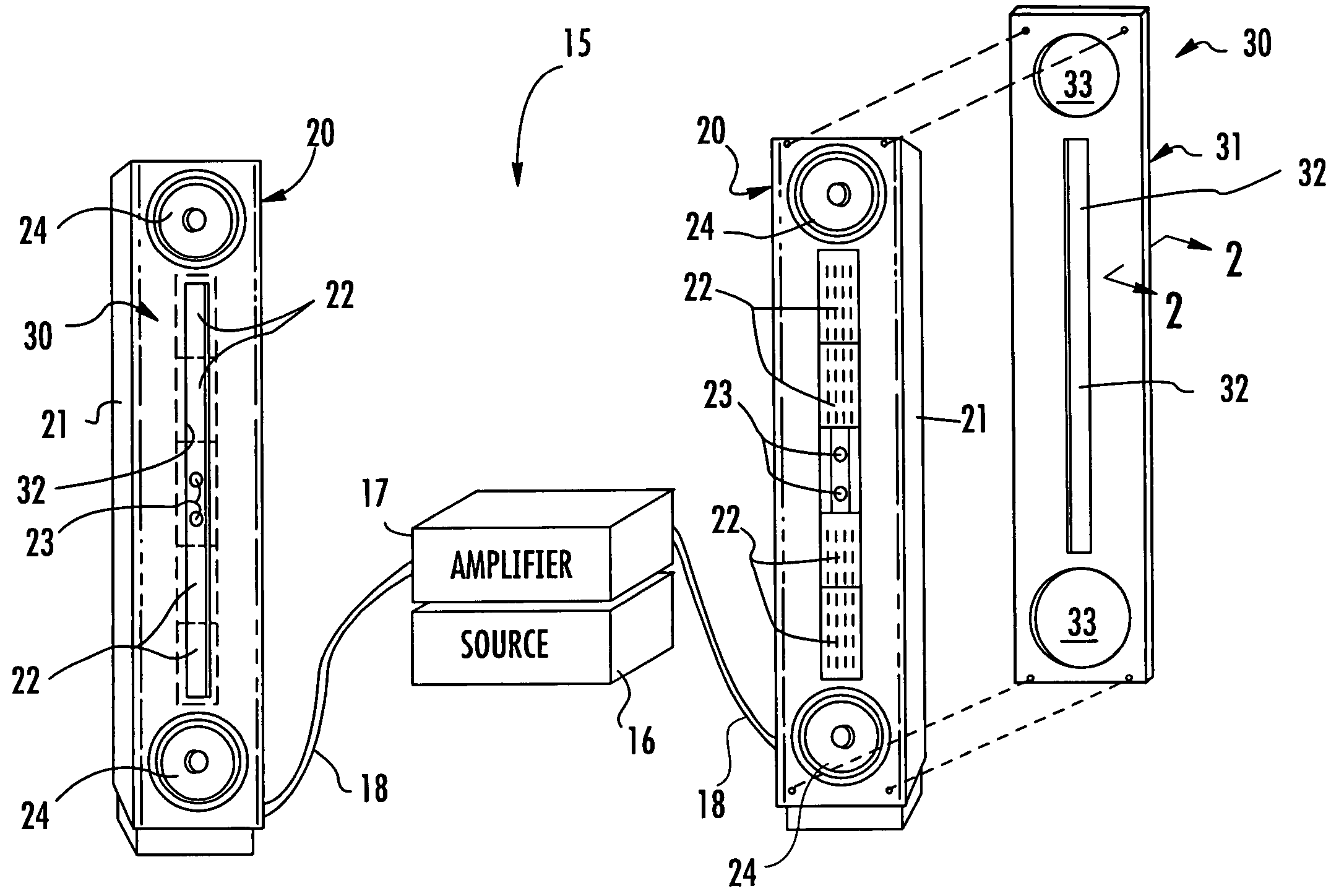
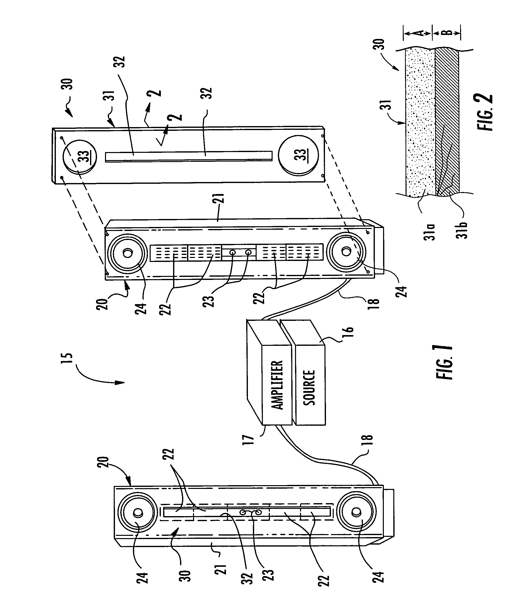
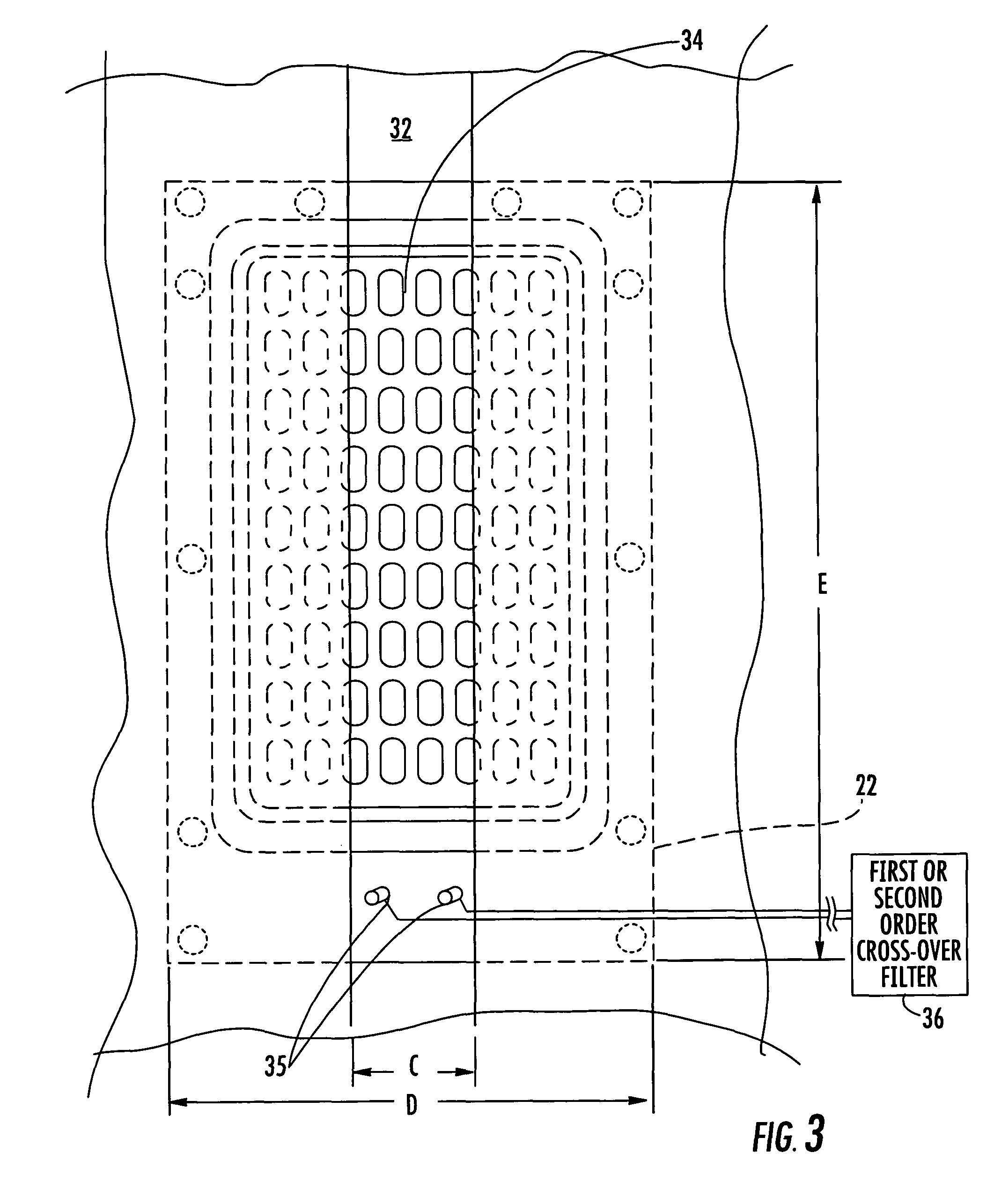
[0022]Referring initially to FIGS. 1-4, a loudspeaker 20 in accordance with the invention is first described. As will be appreciated by those skilled in the art, a typical stereo audio system 15 may include a signal source 16, such as a CD player, and an amplifier 17 connected to the signal source to amplify the signals therefrom. The amplifier 17, in turn, is connected via cables 18 to drive the illustrated pair of spaced apart loudspeakers 20. Of course, the lou...


PUM


Abstract

A loudspeaker may include a baffle, a planar diaphragm transducer carried by the baffle and having a front surface for radiating acoustic energy therefrom, and a slotted waveguide adjacent the front surface of the planar diaphragm transducer. The planar diaphragm transducer may be operable to a desired high frequency, and the slotted opening may have a width not substantially greater than a wavelength corresponding to the desired high frequency. For example, for a desired high frequency of about 20 KHz, the slotted opening may have a width not greater than about two-thirds of an inch. Accordingly, the loudspeaker including the slotted waveguide may provide nearly constant horizontal directivity over a large angle. In another embodiment, the loudspeaker may include a conical diaphragm transducer with a slotted waveguide adjacent its front surface.

Description

FIELD OF THE INVENTION[0001]The present invention relates to the field of loudspeakers, and, more particularly, to loudspeakers and associated methods, such as for the reproduction of high quality music.BACKGROUND OF THE INVENTION[0002]A typical home entertainment audio system includes two or more loudspeakers that serve as transducers to convert electrical signals into acoustic energy to be heard and enjoyed by the listener. A significant advance in speakers has been the use of planar diaphragm or ribbon transducers. A planar diaphragm transducer includes a pair of spaced apart permanent magnet arrays with a movable diaphragm or ribbon therebetween. Electrical conductors are supported on the movable diaphragm and receive the driving signal. Accordingly, the diaphragm moves inwardly and outwardly in a push-pull arrangement with respect to the magnet arrays to convert the electrical energy into acoustic energy or sound. Such planar transducers are disclosed in U.S. Pat. Nos. 5,901,23...

Claims


Application Information

Patent Timeline
Patent Type & Authority Patents(United States)
IPC IPC(8): H04R9/08H04R1/00H04R1/20H05K5/00
CPCH04R1/345
Inventor CHENEY, BRIAN E.
Owner CHENEY BRIAN E
Learn More