Method for restoring airfoil tip contour

a compressor or turbine blade technology, applied in the field of airfoil tip contour restoration, can solve the problems of turbine blade wear, turbine blades that are not easy to repair, and turbine blades that are not easy to repair, and achieve the effect of small radius of curvatur

Active Publication Date: 2010-11-23
RTX CORP
View PDF14 Cites 20 Cited by
  • Summary
  • Abstract
  • Description
  • Claims
  • Application Information

AI Technical Summary

Benefits of technology

[0011]In a disclosed embodiment of this invention, a blade has its airfoil tip repaired by applying a welding material to extend the tip back toward its original height. Excess material is then machined away by using a super abrasive machining (SAM) technique to return the contour of the airfoil to its desired shape. A quill having SAM materials is utilized to return the contour to its original shape. Another SAM tool, such as a grinding wheel, may then be utilized to return the airfoil to its desired height. By utilizing the smaller SAM quill, one can machine a relatively small radius of curvature on the airfoil.

Problems solved by technology

The turbine blades exist in a very harsh environment, and may also be subject to rubbing with spaced stationary surfaces.
The turbine blades as known have very complex structures.
Even with the design of the cooling channels, etc., turbine blades will often wear.
Since the blades are formed with the complex channels, they are expensive.
The compressor blades are not subject to the high temperatures that the turbine blades face, but have their own challenges.
As an example, sand or other impurities can damage the blade.
The prior art techniques are relatively time-consuming.
Moreover, for smaller blades having an airfoil that curves around a smaller radius of curvature, the prior art grinding and machining tools may be too large.
However, super abrasive machining techniques have not been utilized for repairing the tips of blade airfoils.

Method used


Image

  • Method for restoring airfoil tip contour
  • Method for restoring airfoil tip contour
  • Method for restoring airfoil tip contour

Examples


Embodiment Construction

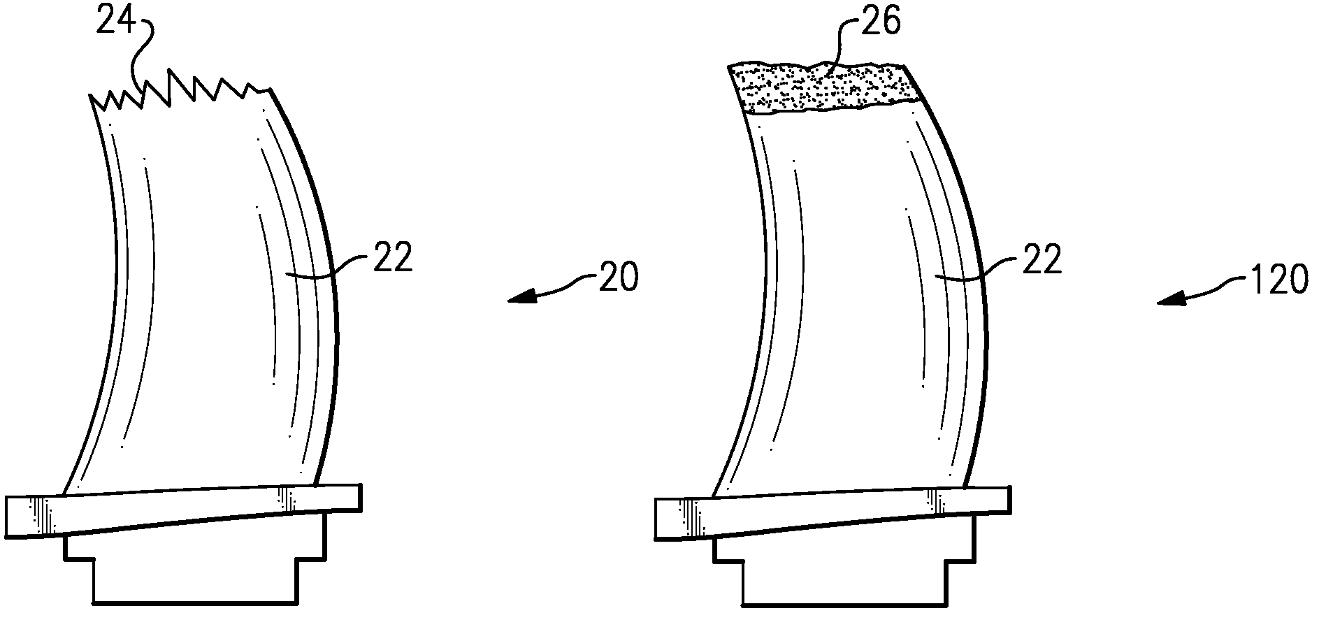
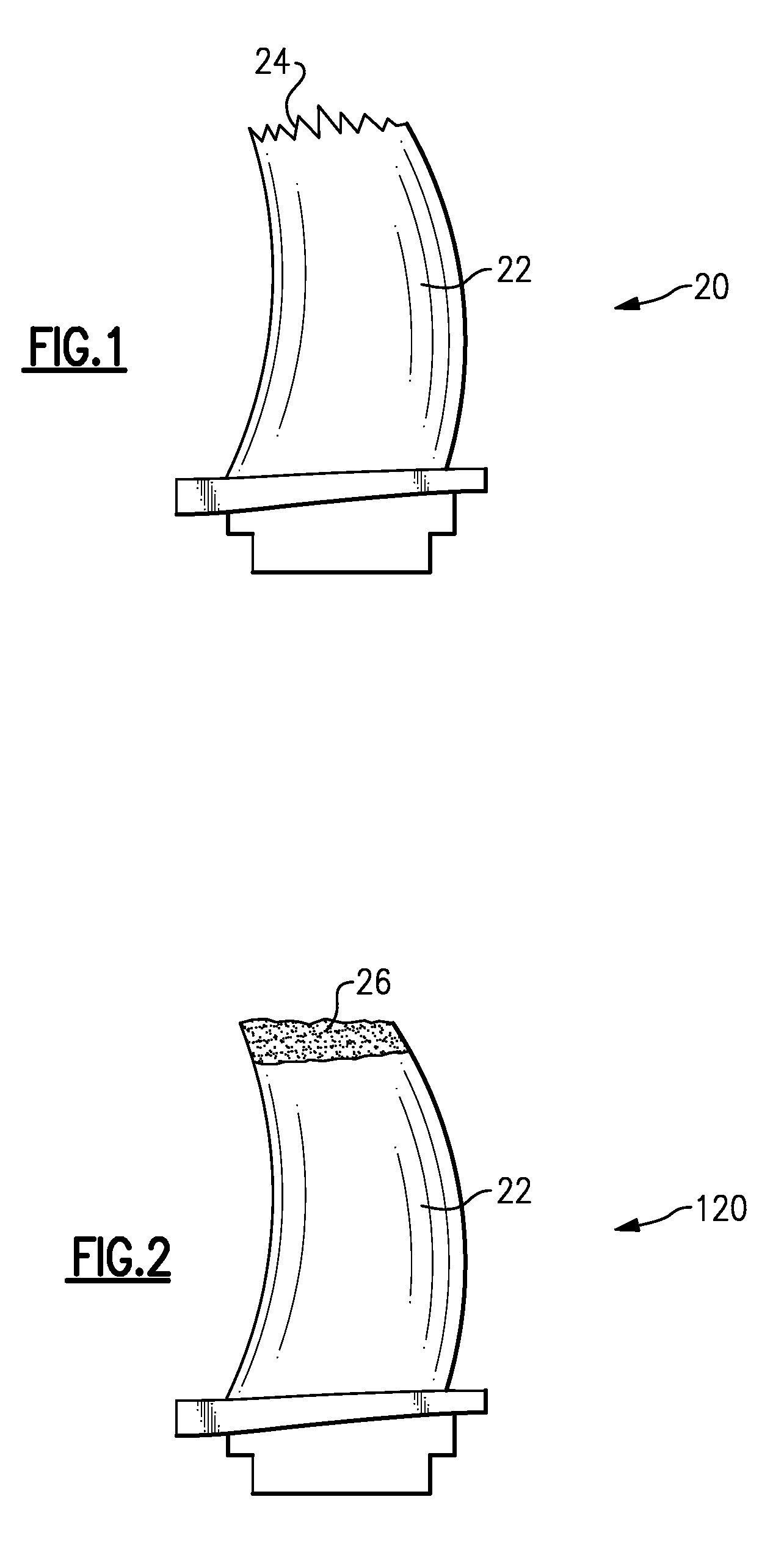
[0021]FIG. 1 shows a worn turbine blade 20. As known, an airfoil 22 extends toward a tip. The tip is shown to be worn at 24. Such a turbine blade 20 will typically be taken out of service for repair. While the drawings show a turbine blade, it should be understood the invention extends to repair of compressor blades also.

[0022]FIG. 2 shows a first step in the repair of the blade 120. As shown, the airfoil 22 now is returned beyond its original height by adding weld material 26 to extend the height from the worn shape 24 of FIG. 1. The weld material is deposited at the tip, but may extend too far, and also would typically not have the desired contour shape for the airfoil 22.

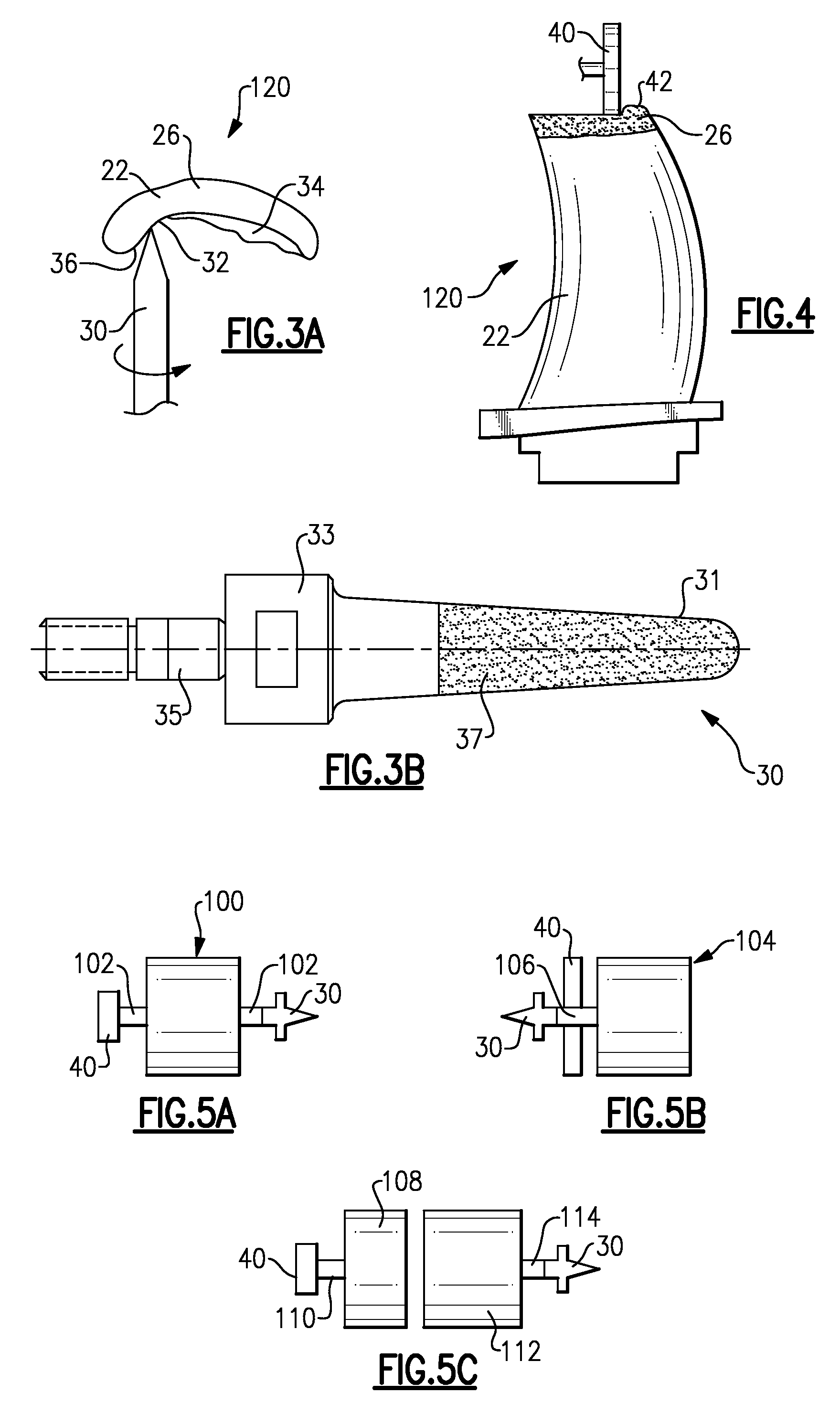
[0023]Thus, as shown in FIG. 3A, a super abrasive machine quill 30 is now used to machine the contour 32 of the airfoil 120. As shown, there may be excess weld material 34 which is cut away by the SAM quill 30 to define the final shape 36.

[0024]FIG. 3B shows a known SAM quill 30. As known, a tip 31 performs the a...


PUM

PropertyMeasurementUnit
heightaaaaaaaaaa
structuresaaaaaaaaaa
temperaturesaaaaaaaaaa

Abstract

A blade is repaired by utilizing a super abrasive machining quill and / or wheel to form the contour and restore the height of the blade. By utilizing super abrasive machining, the contour and height can be quickly returned to desired dimensions by removing unwanted added material.

Description

BACKGROUND OF THE INVENTION[0001]This application relates to a method of repairing a compressor or turbine blade airfoil, wherein super abrasive machining (SAM) quills are utilized to form the contour on the airfoil.[0002]Gas turbine engines are known, and typically include a plurality of sections mounted in series. Two of the sections are the turbine section and the compressor section. These sections each include a plurality of rotors, each mounting a plurality of circumferentially spaced blades.[0003]Air enters a gas turbine engine via a fan. Some air is bypass air, while some air enters a compressor section, where it is compressed. The compressed air moves downstream where it is mixed with fuel and is combusted in a combustor section. The hot products of combustion then move downstream over the turbine blades, driving them to rotate. The turbine blades exist in a very harsh environment, and may also be subject to rubbing with spaced stationary surfaces.[0004]The turbine blades as...

Claims


Application Information

Patent Timeline
Patent Type & Authority Patents(United States)
IPC IPC(8): B23P6/00
CPCB23P6/007B24B19/14F01D5/288Y10T29/49318Y10T29/49726Y10T29/49725Y10T29/49718Y10T29/49336Y10T29/49728Y10T29/49723
Inventor ROSE, WILLIAM M.
Owner RTX CORP
Why Eureka
Try Eureka