Automobile body reinforcement with excellent bending crush characteristics

a technology of automobile body reinforcement and crush characteristics, which is applied in the direction of bumpers, vehicle components, vehicular safety arrangments, etc., can solve the problems of increasing the amount of energy absorption per unit deformation of the automobile body reinforcement, the automobile body reinforcement is not easily buckled or bent, and the damage to the automobile body decreases, so as to improve the crush strength of the front wall, improve the bending strength and energy absorption. , the effect of increasing the width-thickness ratio

Inactive Publication Date: 2010-11-23
KOBE STEEL LTD
View PDF21 Cites 18 Cited by
  • Summary
  • Abstract
  • Description
  • Claims
  • Application Information

AI Technical Summary

Benefits of technology

[0071]Compared with the invention example 2, the invention example 1 does not appear so much advantageous over the comparison-purpose example 3 as to the energy absorption amount and initial buckling load. The only difference between the invention example 1 and invention example 2 is in the depth (represented by length l shown in FIG. 3) of the concave portion (10a in the invention example 1 and 10b in the invention example 2) toward the rear wall 2. Namely, the concave portion 10b (shown in FIG. 2) of the invention example 2 is deeper than the concave portion 10a (shown in FIG. 1) of the invention example 1. Thus, comparison between the invention examples 1 and 2 and the comparison-purpose example 3 indicates that the energy absorption amount and the value of initial buckling load are affected by the depth of the concave portion 10a or 10b. The concave portion 10a of the invention example 1 may be regarded as indicating a minimum significant depth of such a concave portion. It also exemplifies that, to obtain an optimum effect of the concave portion, an optimum depth of the concave portion requires to be determined. The embodiment results described above clarify the advantageous effects of the present invention and the significance of the bumper reinforcement structure of the present invention.
[0072]The invention example 4 represented by a bold chain-line curve in FIG. 8 represents a bumper reinforcement having a rear wall 2 thicker than a front wall 1. Increasing the thickness of the rear wall 2 increases the strength and rigidity of a central portion of the rear wall 2, at which the load generated at a time of a pole collision tends to concentrate and which is therefore easily cracked, and thereby prevents the central portion from being easily cracked. This enables the bumper reinforcement to fully display its performance. Generally, there can be cases where, depending on the condition of collision with a pole, the central portion of the rear wall 2 is cracked and, as a result, the bumper reinforcement is disabled. The invention example 4 having the rear wall 2 with an increased thickness prevents the central portion of the rear wall 2 from being easily cracked and thus enables the bumper reinforcement to display its performance.
[0073]Furthermore, in the invention example 4 in which the rear wall 2 has an increased thickness, the front wall 1 has a correspondingly decreased thickness. This is to make up for the weight increase caused by increasing the thickness of the rear wall 2 or to minimize such a weight increase and keeps the bumper reinforcement light as the unit weights (g / m) listed in Table 1 show. A bumper reinforcement can also have a rear wall with an increased thickness without, unlike what is done for the invention example 4, correspondingly reducing the thickness of its front wall. It then becomes possible to increase the maximum load that can be applied to the bumper reinforcement and slow down dropping of the load from its maximum level. In this way, the amount of energy absorption by the bumper reinforcement can be increased. As described above, the present invention can generate superior effects making it possible, by adjusting the thicknesses of the rear wall 2 and front wall 1, to flexibly adjust or design the performance of the bumper reinforcement as to, for example, the maximum applicable load and the amount of energy absorption while taking into consideration the weight of the bumper reinforcement.
[0074]TABLE 1Bumper reinforcement conditionsPole collision characteristics of bumperWall thickness (mm)reinforcementUpper wall 3,Length lEnergylower wall 4,(mm) ofInitialabsorption (kJ)MaximumFrontRearIntermediateconcaveCross-sectionalProjectionUnit weightbuckling(at 100 mmmomentNo.wall 1wall 2lib 5portion 10shape(mm)g / mload kNdisplacement)kN · m14.64.43.011.8FIG. 112497576.96.0021.224.64.43.020.0FIG. 212503175.16.2920.734.64.43.0—FIG. 612500678.56.0021.644.44.62.620.0FIG. 212485573.55.5020.2
[0075]FIG. 9 shows relationships between the flange widths Wd (flange projection in mm represented by horizontal axis) of the example bumper reinforcements listed in Table 1 and performance items (initial buckling load in kN represented by the left vertical axis, and energy absorption amount in kJ at a displacement of 100 mm represented by the right vertical axis). For the analysis, results of which are shown in FIG. 9, the cross-sectional dimensions of the bumper reinforcements were assumed to be the same as listed in Table 1, but the flange width Wd (indicated as flange projection along the horizontal axis in FIG. 9) of each bumper reinforcement was varied from 5 mm to 15 mm (in Table 1, Wd is constant at 12 mm).
[0076]In FIG. 9, the analysis results on the invention examples 1 and 2 having the concave portions 10a and 10b mutually differing in concave portion length l and the comparison-purpose example 3 are compared in the same graph. As for the initial buckling load represented by the left vertical axis, as the lower three data curves denoted by a left-pointing arrow show, the values indicated for the invention

Problems solved by technology

Therefore, even when the automobile including the automobile body reinforcement collides with a pole generating a load which is approximately horizontally applied concentratedly to the portion subjected to the collision of the automobile body reinforcement, the automobile body reinforcement is not easily buckled or bent.
Since the decrease in the reactive load following the generation of a maximum impact load becomes relatively small, the amount of energy absorption per unit deformation by the automobile body reinforcement increases and damage to the automobile body decreases.

Method used


Image

  • Automobile body reinforcement with excellent bending crush characteristics
  • Automobile body reinforcement with excellent bending crush characteristics
  • Automobile body reinforcement with excellent bending crush characteristics

Examples


embodiments

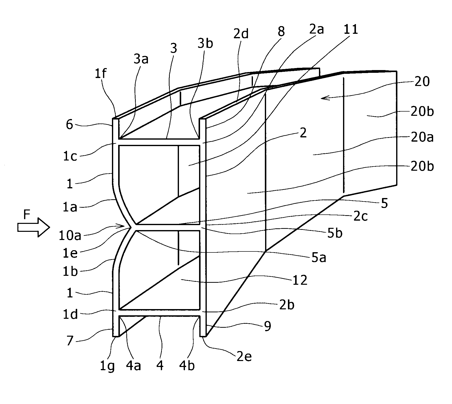
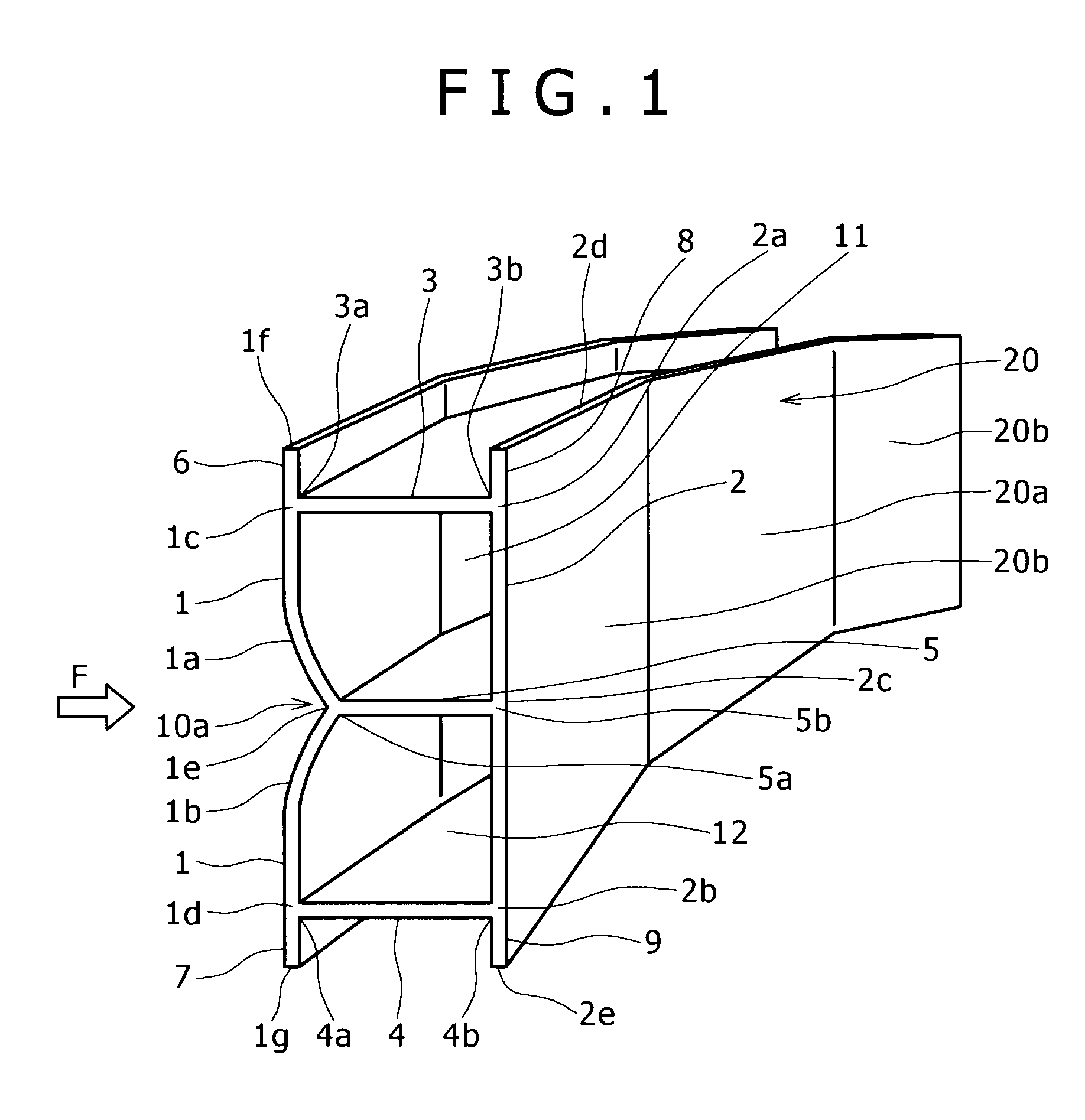
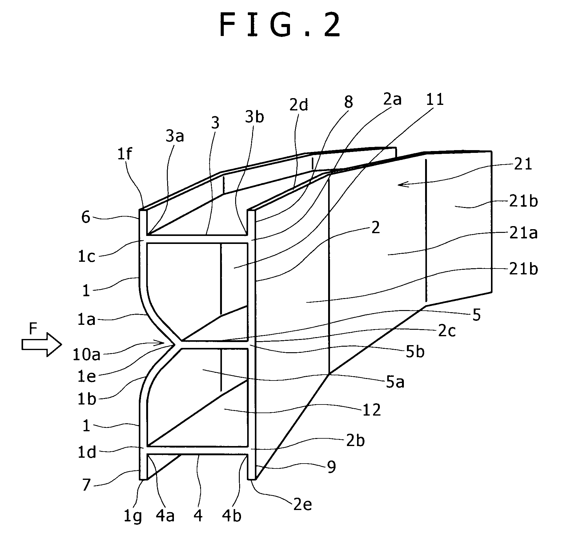
[0066]Experiments were carried out to evaluate, in terms of pole collision strength, the example bumper reinforcements shown in FIGS. 1 and 2 of the present invention and the example bumper reinforcement shown, for comparison purposes, in FIG. 6.

[0067]For the experiments, a pole collision was simulated as follows. A bumper reinforcement collides, at a front middle portion thereof, with a rigid pole with a radius of 127 mm. Based on the simulation, the initial buckling load applied to a local area of the front middle portion, the load energy absorption performance of the bumper reinforcement, and the bending moment generated in the bumper reinforcement were analyzed. Even though the vehicle was assumed to weigh 1.0 to 1.8 tons and collide with a pole at a speed of 8 to 64 km / h, the analysis was made based on static compression experiments.

[0068]As for the cross-sectional shape, with reference to FIG. 3, each bumper reinforcement was assumed to have a front wall vertical width Wa of 4...


PUM


Abstract

An automobile body reinforcement including a hollow aluminum alloy extrusion having an approximately rectangular cross-section is structured as follows: (a) a front wall, a rear wall, an upper horizontal wall, a lower horizontal wall, and an intermediate horizontal wall are provided; (b) the front and rear walls are each at least 3 mm thick; (c) the upper and lower horizontal walls divide each of the front and rear walls thereby defining upper and lower end portions of each of the front and rear walls as flange portions; and (d) the front wall has a concave portion formed in a middle portion thereof and the concave portion is connected to a front end of the intermediate wall. The aluminum alloy automobile body reinforcement structured as described above that may be, for example, a bumper reinforcement or a door guard bar has high bending crush characteristics, for example, high bending strength and high energy absorbability against the bending load generated at a time of a vehicle collision and can provide high collision safety without requiring an additional reinforcement.

Description

BACKGROUND OF THE INVENTION[0001]1. Field of the Invention[0002]The present invention relates to an aluminum alloy automobile body reinforcement, for example, a bumper reinforcement or a door guard bar which has, as its bending crush characteristics, high bending strength and high energy absorbability against the bending load generated at a time of a vehicle collision and which can provide high collision safety without requiring an additional reinforcement.[0003]2. Description of the Related Art[0004]As is well known, an automobile body is provided with many automobile body reinforcements such as bumper reinforcements and door guard bars. For example, each of the bumpers attached to a front end portion and a rear end portion of an automobile body is, as widely known, internally provided with a bumper reinforcement (also referred to as a bumper armature) for strengthening the bumper. Such a bumper reinforcement has an approximately rectangular cross-section. It is, as well known, pos...

Claims


Application Information

Patent Timeline
Patent Type & Authority Patents(United States)
IPC IPC(8): B60R19/02
CPCB60R19/18B60R2019/182
Inventor HASHIMURA, TORU
Owner KOBE STEEL LTD
Why Eureka
Try Eureka