
Communication method and system for the transmission of time-driven and event-driven Ethernet messages

a communication method and event-driven technology, applied in transmission systems, hybrid switching systems, transmission systems, etc., can solve the problems of poor clock synchronization accuracy, inability to substantially improve the real-time properties of the ethernet protocol, so as to improve the precision of clock synchronization and improve the real-time properties of the communication system. , the effect of improving the accuracy of control engineering precision

Active Publication Date: 2010-11-23
TTTECH COMPTECHN
View PDF25 Cites 42 Cited by
  • Summary
  • Abstract
  • Description
  • Claims
  • Application Information

AI Technical Summary

Benefits of technology

[0024]By guaranteeing a constant delay time, it is possible to achieve a high control engineering precision. The constant delay time is therefore of special significance for the reason that, as is known from the theory of clock synchronization, the variability of the delay time (this is the difference between the maximum and minimum delay times) makes the precision of the clock synchronization worse. An a priori known constant delay time can be considered in the clock synchronization algorithm and therefore has no effect on the precision of the clock synchronization. An imprecise clock synchronization brings about a poor time basis because the granularity of the global time must be greater than the precision of the clock synchronization. A coarse granularity of the clocks brings about an imprecise time resolution of events. Furthermore, the variability of the delay time also determines the precision of the synchronization of distributed actions in a distributed computer system.
[0025]The present invention makes it possible to improve substantially the real-time properties of a communication system. This new communication system supports the parallel operation of event-triggered and time-triggered Ethernet messages in a single communication system. In the following, the classical Ethernet messages are characterized as ET (event-triggered) messages and the time-triggered Ethernet messages as TT (time-triggered) messages. The TT messages have a constant delay time and minimal jitter.
[0026]The following significant economic advantages are produced by the invention. The minimal jitter of the TT-messages enables the development of closed-loop control circuits of high control engineering quality. The TT messages enable the development of a global time with good precision. Global time supports the generation of precise local time stamps in the data acquisition and makes it possible to improve the temporal specification of the interfaces. Moreover, conventional Ethernet controllers may be used without modification.
[0027]The method of the invention can be produced especially simply if the constant delay time is selected in such a manner that the output channels of the star coupler may be cleared for the transport of the TT message to be received.

Problems solved by technology

For these cost reasons, Ethernet is also used increasingly in real-time data processing, although the existing Ethernet protocol possesses no good real-time properties, such as minimal jitter.
However, the real-time properties of the Ethernet protocol cannot be substantially improved with the procedure proposed here by itself.
An imprecise clock synchronization brings about a poor time basis because the granularity of the global time must be greater than the precision of the clock synchronization.

Method used


Image

  • Communication method and system for the transmission of time-driven and event-driven Ethernet messages
  • Communication method and system for the transmission of time-driven and event-driven Ethernet messages
  • Communication method and system for the transmission of time-driven and event-driven Ethernet messages

Examples


Embodiment Construction

[0051]In the next section, an embodiment of the new method is shown by an example with four network node computers, which are connected via two replicated star couplers.

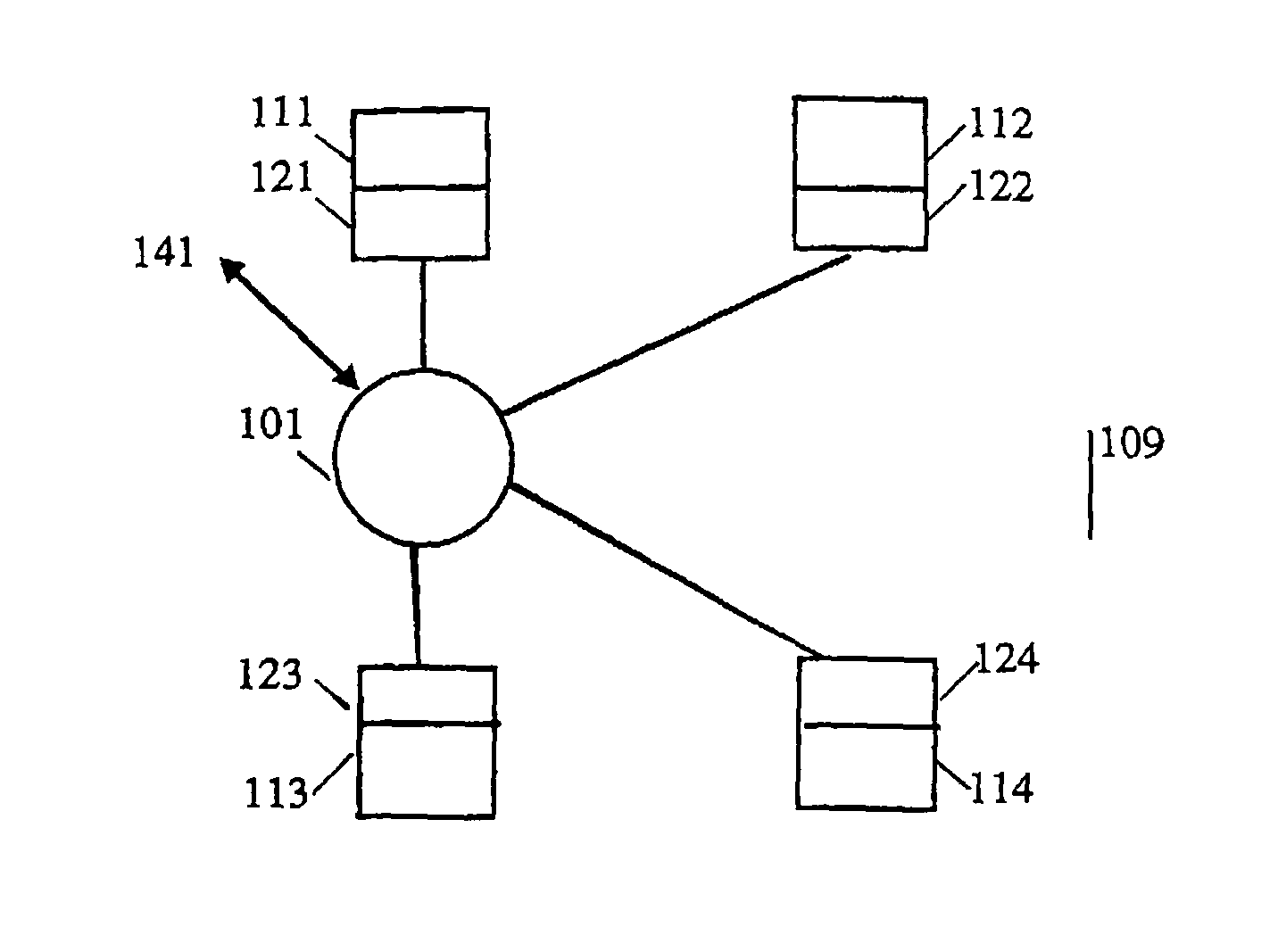
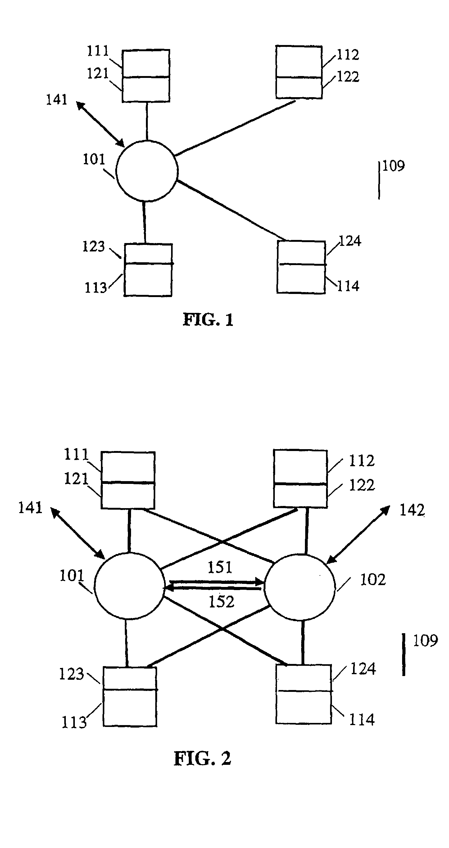
[0052]FIG. 1 shows a distributed computer system with a star coupler. It comprises four network node computers 111, 112, 113, and 114, each of which has a communication controller 121, 122, 123, and 124 with one bi-directional communication channel connection each, and which are connected via a communication system comprising a communication channel 109. Located in this communication channel is an intelligent star coupler 101 for the central control of communication. The star coupler 101 can be initialized and observed via an optional, separate communication channel 141.

[0053]FIG. 2 shows a distributed fault-tolerant computer system having two star couplers. It is comprised of four network node computers 111, 112, 113 and 114, each of which has a communication controller 121, 122, 123 and 124 with two bi-directional ...


PUM


Abstract

A communication method for transmitting Ethernet messages in a distributed real-time system in which a plurality of network node computers, e.g. four network node computers (111, 112, 113, 114), each comprising at least one communication controller (121, 122, 123, 124), are linked via a communication system comprising one or more communication channels (109), one or more intelligent star couplers (101, 102) being disposed in each communication channel. According to the invention, a distinction is made between conventional Ethernet messages (ET messages) and time-triggered Ethernet messages (TT messages), the TT messages being transported with an a priori known constant delay time (Δ) between transmitter and receiver, and, when there is a time conflict between ET and TT messages, the transport of the ET message that is in conflict being delayed or aborted in order to be able to transport the TT message with the constant delay time (Δ). Furthermore, the invention relates to a corresponding communication system and a star coupler for such a communication system.

Description

CROSS-REFERENCE TO RELATED APPLICATIONS[0001]This application claims priority from PCT Patent Application Serial No. AT03 / 00164, filed 4 Jun. 2003, which claims priority from Austrian Patent Application A895 / 2002, filed 13 Jun. 2002.FIELD OF THE INVENTION[0002]The invention relates to a communication method for transmitting Ethernet messages in a distributed real-time system in which a plurality of network node computers, e.g. four network node computers, each comprising at least one communication controller, are linked via a communication system comprising one or more communication channels, one or more intelligent star couplers being disposed in each communication channel, and a distinction being made between conventional Ethernet messages (ET messages) and time-triggered Ethernet messages (TT messages) and the TT messages being transported with an a priori known constant delay time between transmitter and receiver.BACKGROUND OF THE INVENTION[0003]Such a method is known from WO 01...

Claims


Application Information

Patent Timeline
Patent Type & Authority Patents(United States)
IPC IPC(8): H04L1/00H04L12/26H04L12/28H04L12/56H04J3/06H04L12/44H04L12/64H04L47/2416
CPCH04J3/0655H04L12/40013H04L12/40026H04L12/40143H04L12/6402H04L47/2416H04L2012/445H04L2012/641H04L12/44H04L12/28
Inventor KOPETZ, HERMANN
Owner TTTECH COMPTECHN
Learn More