
Methods and apparatus for unidirectional timing message transport over packet networks

a packet network and message technology, applied in electrical equipment, digital transmission, time-division multiplex, etc., can solve the problems of long synchronization time, inability to tolerate pdv at high orders of magnitude, and protocol poor tolerance for uncertain and variable delay, etc., to achieve high variation of propagation delay

Active Publication Date: 2010-11-23
AVAGO TECH INT SALES PTE LTD
View PDF8 Cites 4 Cited by
  • Summary
  • Abstract
  • Description
  • Claims
  • Application Information

AI Technical Summary

Benefits of technology

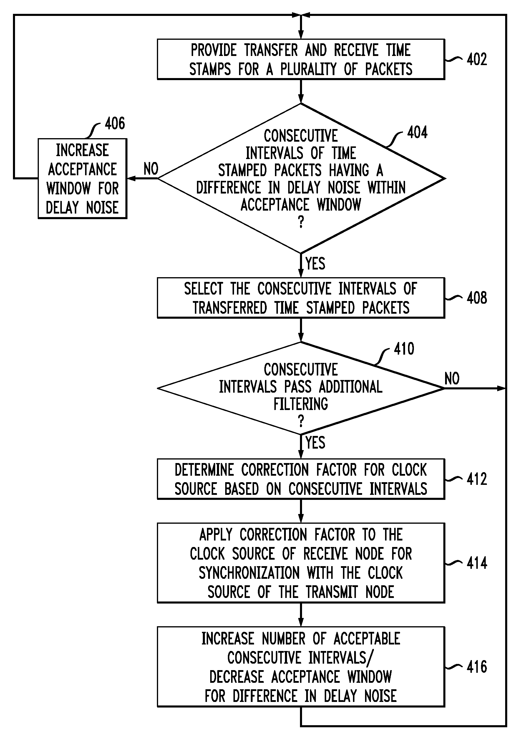
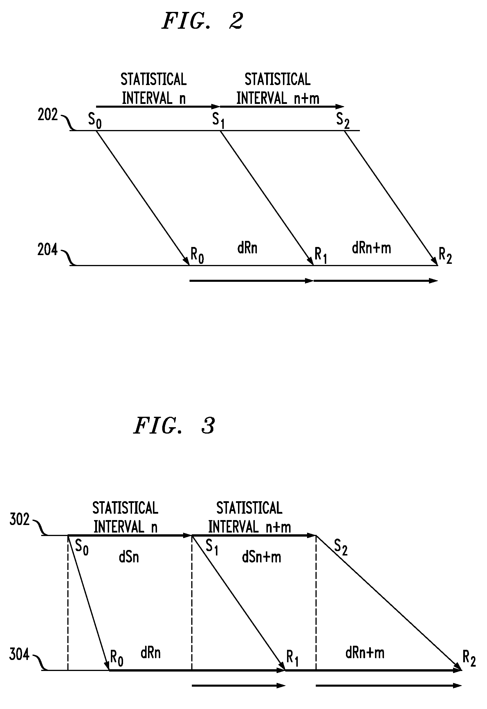
The present invention provides a method for synchronizing clocks in a packet network with high variation of propagation delay. This is achieved by selecting consecutive intervals of transferred time-stamped packets with a difference in delay noise within a defined acceptance window. A correction factor is determined for the second clock based on the transmit and receive time stamps of the consecutive intervals and applied to synchronize the second clock with the first clock. The method is fast and tolerates high PDV, providing better frequency synchronization.

Problems solved by technology

However, standard time synchronization protocols can be inaccurate and typically result in long synchronization times. Further, such protocols have very poor tolerance for the uncertain and varying delay of synchronization signals from the transmit node to the receive node of the packet transfer network, commonly known as packet delay variation (PDV).
However, IEEE 1588 is not capable of tolerating PDV at high orders of magnitude.
Further the bidirectional message transmittal is slower and less accurate in determining synchronization times.

Method used


Image

  • Methods and apparatus for unidirectional timing message transport over packet networks
  • Methods and apparatus for unidirectional timing message transport over packet networks
  • Methods and apparatus for unidirectional timing message transport over packet networks

Examples


Embodiment Construction

[0015]As will be described in detail below, the present invention in the illustrative embodiment relates generally to the field of packet transfer networks and, more particularly, to improved techniques for the transmission of precision timing information from a first clock source to a second clock source over packet networks having propagation delay. The illustrative embodiment extracts a correction factor from consecutive intervals of time-stamped packets having a difference in delay noise within a defined acceptance window.

[0016]Referring initially to FIG. 1, a diagram illustrates a packet transfer system, according to an embodiment of the present invention. A transmit node 102 includes a transmit clock 104, or master clock, in communication with a transmit node processor 106. Packets including data and timing information are transferred through a network 108 to a receive node 110. Receive node 110 includes a receive clock 112, or slave clock, in communication with a receive node...


PUM


Abstract

Methods and apparatus for synchronizing a first clock of a transmit node and a second clock of receive node in a packet network are provided. Consecutive intervals of time-stamped packets transferred from the transmit node to the receive node are selected. The consecutive intervals have a difference in delay noise within a defined acceptance window. A correction factor is determined for the second clock in accordance with transmit and receive time stamps of transferred time-stamped packets bounding the consecutive intervals. The correction factor is applied to the second clock to synchronize the second clock of the receive node with the first clock of the transmit node.

Description

FIELD OF THE INVENTION[0001]The present invention relates generally to packet transfer networks and, more particularly, to timing information transmission over packet networks.BACKGROUND OF THE INVENTION[0002]In order to synchronize clock sources on both ends of a packet transfer network, timing information is transmitted between a clock source of a transmit node and a clock source of a receive node. However, standard time synchronization protocols can be inaccurate and typically result in long synchronization times. Further, such protocols have very poor tolerance for the uncertain and varying delay of synchronization signals from the transmit node to the receive node of the packet transfer network, commonly known as packet delay variation (PDV).[0003]One such example of an existing time synchronization protocol is the Standard Precision Time Protocol (PTP) IEEE 1588. IEEE 1588 utilizes two phases in a synchronization process. The first phase corrects the time difference between th...

Claims


Application Information

Patent Timeline
Patent Type & Authority Patents(United States)
IPC IPC(8): H04J3/06
CPCH04J3/0664H04L43/0864H04L43/106H04J3/06H04L7/00
Inventor RADULESCU, CODRUT RADU
Owner AVAGO TECH INT SALES PTE LTD
Learn More