
Power control of a wind farm and method thereof

a technology of power control and wind farm, applied in the field of wind farm, can solve the problems of low efficiency of wind farm, and low efficiency of wind farm, and achieve the effects of reducing complexity in circuitry, high dynamic, and good results

Active Publication Date: 2010-11-23
SIEMENS GAMESA RENEWABLE ENERGY SERVICE GMBH
View PDF9 Cites 19 Cited by
  • Summary
  • Abstract
  • Description
  • Claims
  • Application Information

AI Technical Summary

Benefits of technology

The invention is a wind farm and a method for controlling it that avoids the disadvantages of previous wind farms. The wind farm has multiple wind energy installations and a wind farm master that controls the output of the power generated by the wind energy installations. The wind energy installations have generators that convert mechanical energy into electrical energy. The wind farm master has a power control device with two loops: a fast loop and a slow loop. The fast loop has a higher dynamic than the slow loop and is designed to respond quickly to changes or faults. The slow loop is designed to ensure steady-state accuracy over a long period of time. The invention combines the benefits of fast control with the benefits of slow control, such as resistance to vibrations and the ability to compensate for faults. The multi-loop control device is designed to be a wattless power control device, which means it does not require a separate control device for each wind energy installation. This simplifies the system and reduces complexity.

Problems solved by technology

The connection of such wind farms with a high power to electrical energy supply systems is not without problems.
An example of such faults are voltage dips, which may arise as a result of a short circuit or as a result of a sudden failure of power station power.
One disadvantage of this known arrangement is the fact that it sometimes responds very slowly to changed requirements.
Although the wind farm master is generally provided with a sufficiently high computation power, the transmission of the control signals to the individual wind energy installations requires a comparatively large amount of time.
Although generally separate communications lines are provided, considerable delays result.
Owing to these long delay times, the behavior of the wind farm is not optimal in the event of changed requirements.
In addition, owing to the long delay times, fluctuations in the control behavior may arise.

Method used


Image

  • Power control of a wind farm and method thereof
  • Power control of a wind farm and method thereof
  • Power control of a wind farm and method thereof

Examples


Embodiment Construction

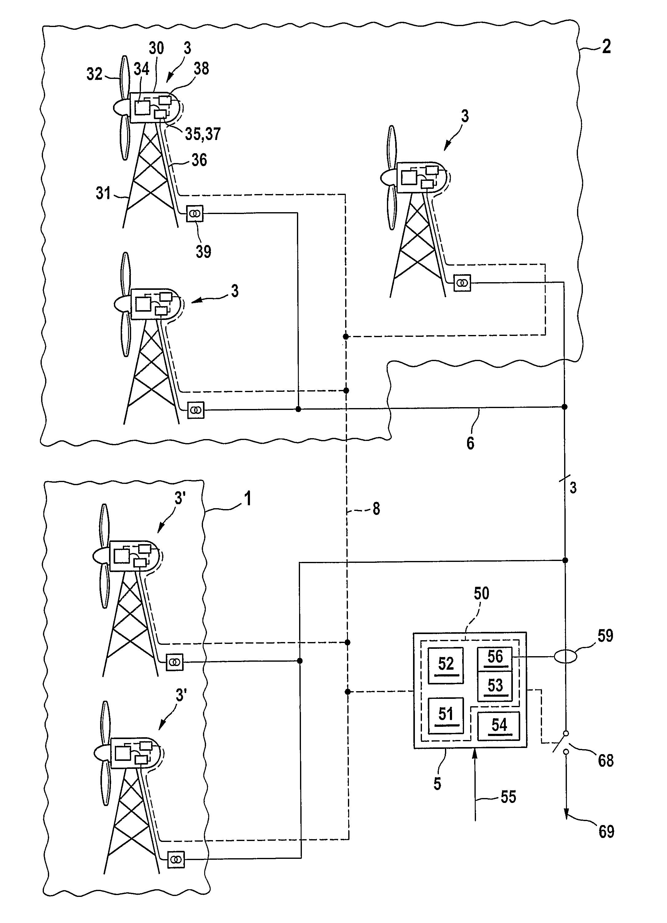
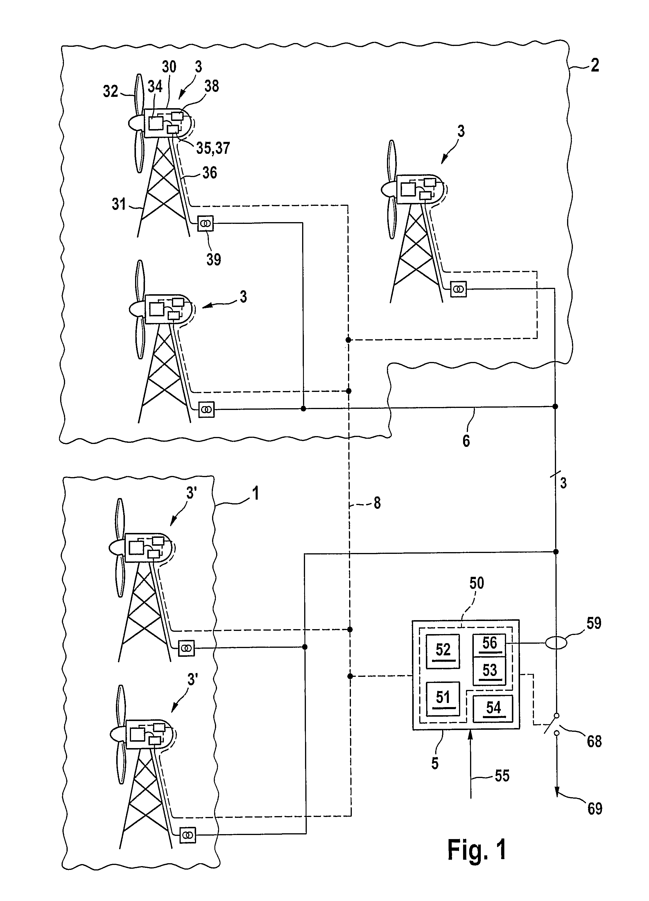
[0030]FIG. 1 illustrates an exemplary embodiment of a wind farm according to the invention. It comprises a plurality of wind energy installations 3 and a central control computer (wind farm master) 5. The wind energy installations 3 are connected to a wind farm-internal bus system 6, which is connected to an electrical power supply system (not illustrated) of an energy supply company via a connection point 69.

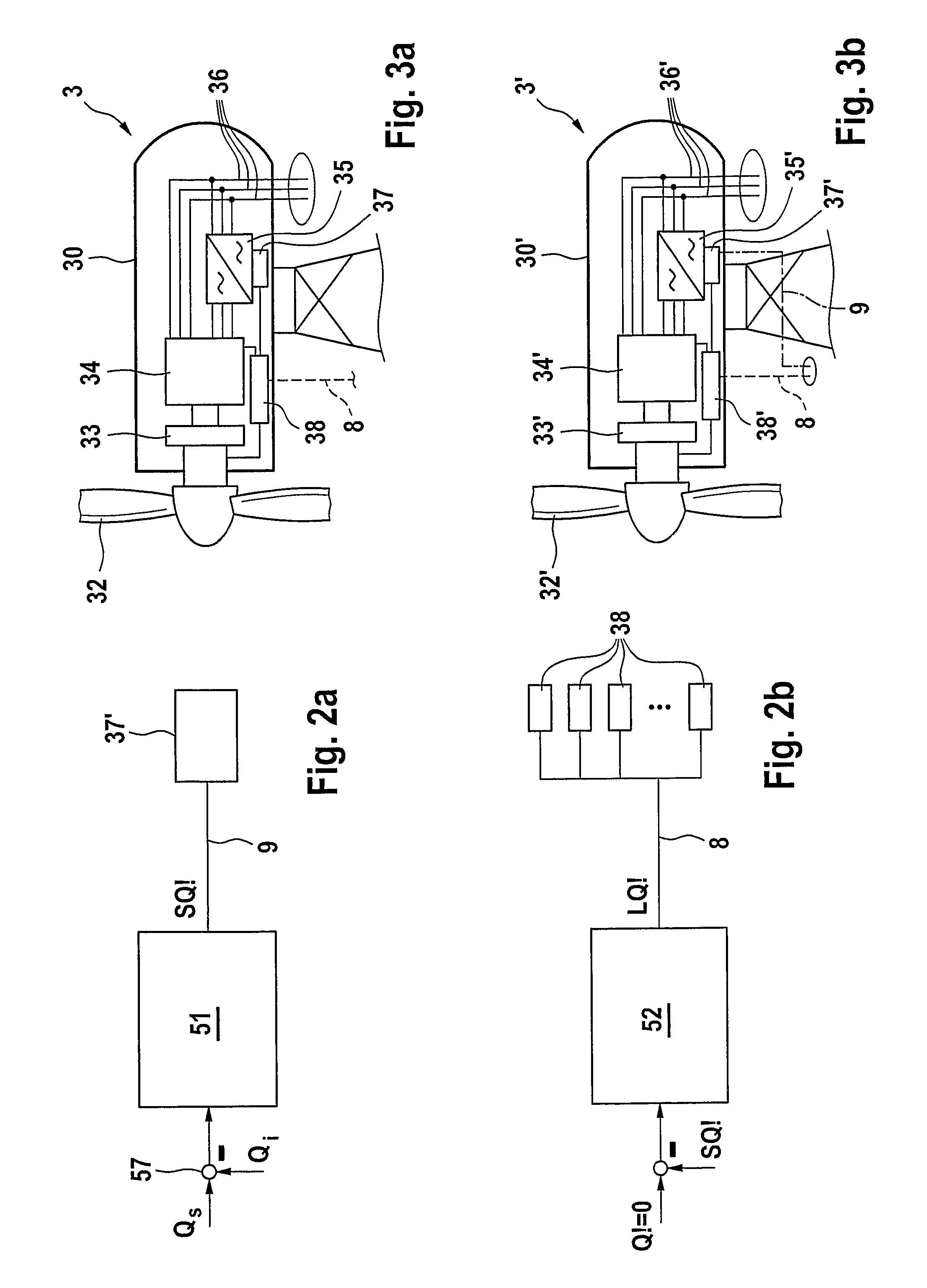
[0031]The design of a wind energy installation 3 will be explained by way of example with reference to FIGS. 1 and 3a. The wind energy installations 3 comprises a machine housing 30, which is arranged pivotably on a tower 31. A rotor 32 is arranged rotatably on an end side of the machine housing 30. The rotor 32 drives a generator 34 via a rotor shaft and a gear mechanism 33. The generator is preferably a double-fed asynchronous generator, but other designs are also possible. A converter 35 and output lines 36 for the generated electrical energy are connected to the generator 3...


PUM


Abstract

A wind farm includes a plurality of wind energy installations which generate electrical energy to be output to a power supply system and a wind farm master for controlling the wind energy installations. Each wind energy installation includes a generator which is driven by a rotor, and the wind farm master includes a power control device having a plurality of loops. This plurality of loops includes a fast loop that includes a controller which acts on a first group of the wind energy installations and a slow loop that includes a controller which acts on a second group of the wind energy installations, the fast controller having a substantially higher dynamic than the slow controller.

Description

REFERENCE TO RELATED APPLICATIONS[0001]This application is a national stage application under 35 USC 371 of International Application No. PCT / EP2005 / 013508, filed Dec. 15, 2005, which claims the priority of German Application No. 10 2004 060 943.8, filed Dec. 17, 2004, the contents of both of which prior applications are incorporated herein by reference.FIELD OF THE INVENTION[0002]The invention relates to a wind farm having a plurality of wind energy installations and a wind farm master for controlling the wind energy installations, the wind energy installations having a generator, which is driven by means of a rotor, for generating electrical power, and the wind farm master having a power control device.BACKGROUND OF THE INVENTION[0003]In recent times, wind energy installations are preferably not installed individually, but combined in groups as wind farms. Usually, such wind farms are positioned at locations which are particularly favorable in terms of wind, such as at the coast o...

Claims


Application Information

Patent Timeline
Patent Type & Authority Patents(United States)
IPC IPC(8): H04J3/18F03D9/00G05D17/00
CPCF03D7/043F03D7/047F03D7/048H02J3/386Y02E10/723Y02E10/763H02J2300/28H02J3/381Y02E10/76Y02E10/72
Inventor ALTEMARK, JENSBECKER, HOLGERFRIEDERICH, SEBASTIAN
Owner SIEMENS GAMESA RENEWABLE ENERGY SERVICE GMBH
Learn More