Wake-on-LAN design in a load balanced environment

Active Publication Date: 2010-11-23
NVIDIA CORP
View PDF8 Cites 15 Cited by
  • Summary
  • Abstract
  • Description
  • Claims
  • Application Information

AI Technical Summary

Benefits of technology

[0010]One advantage of the disclosed method and system is to address the potential problems of not

Problems solved by technology

However, problems arise when the Wake-on-LAN (WOL) proto

Method used


Image

  • Wake-on-LAN design in a load balanced environment
  • Wake-on-LAN design in a load balanced environment
  • Wake-on-LAN design in a load balanced environment

Examples


Embodiment Construction

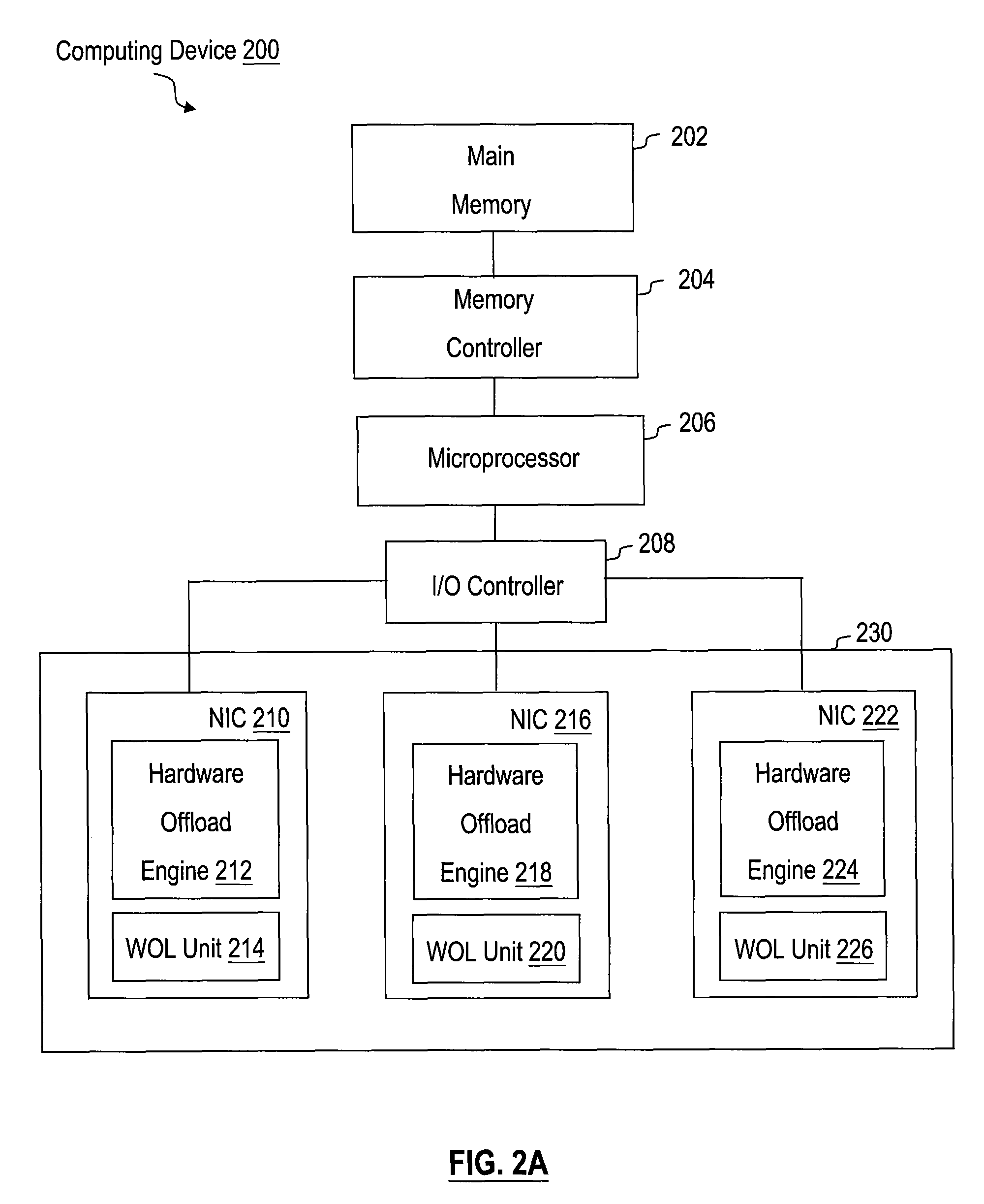
[0018]FIG. 2A illustrate a computing device 200 in which one or more aspects of the present invention can be implemented. The computing device 200 may be a desktop computer, server, laptop computer, palm-sized computer, personal digital assistant, tablet computer, game console, cellular telephone, or any other type of similar device that processes information. As shown, the computing device 200 includes a main memory 202, a memory controller 204, a microprocessor 206, an I / O controller 208, and NICs 210, 216, and 222. Each of the NICs optionally includes its own hardware offload engine (“HOE”) and WOL unit. The HOE includes logic configured for processing network frames associated with network connections between the computing device 200 and one or more remote network computing devices (not shown) that have been selectively offloaded to the NICs. By processing network frames with HOEs 212, 218, and 224 (sometimes referred to as “handling connections in hardware”) rather than perform...


PUM


Abstract

A method and system for supporting Wake-on-LAN (WOL) in a team of network interface cards (NICs) in a computing device is disclosed. One embodiment of the present invention sets forth a method, which includes the steps of programming each of the NICs on the team with a team Media Access Control (MAC) address after having backed up the NIC MAC addresses of the NICs but before the computing device enters a low power state, and causing modification of address resolution protocol (ARP) caches associated with a plurality of client devices coupled to the team of NICs to use the team MAC address.

Description

BACKGROUND OF THE INVENTION[0001]1. Field of the Invention[0002]Embodiments of the present invention relate generally to network communications and more specifically to a method and system for performing wake-on-LAN functionality in a load balanced environment.[0003]2. Description of the Related Art[0004]Unless otherwise indicated herein, the approaches described in this section are not prior art to the claims in this application and are not admitted to be prior art by inclusion in this section.[0005]Performance and reliability are key requirements for modern computer networks. One approach is to create a “team” of network interface cards (“NICs”) to handle the networking needs of a computing device. The team operates in a load-balanced environment to avoid overloading of any one specific NIC on the team and also employs techniques such as “failover” to redirect network traffic from one unreliable NIC to other reliable NICs on the team. These NICs are transparent to the operating sy...

Claims


Application Information

Patent Timeline
IPC IPC(8): G06F15/16G06F3/00
CPCH04L49/90H04L45/28H04L45/583
Inventor ABDULLA, AYAZNANDA, SAMEER
Owner NVIDIA CORP
Why Eureka
Try Eureka