Nitride semiconductor device and method of manufacturing the same

a technology of semiconductor devices and semiconductors, applied in semiconductor/solid-state device manufacturing, semiconductor devices, electrical equipment, etc., can solve problems such as difficulty in manufacturing laser diodes, and achieve the effects of stable operation and output, reduced operation voltage for laser diodes, and reduced variations in the properties of laser diodes due to heat produced during operation

Active Publication Date: 2010-11-30
MITSUBISHI ELECTRIC CORP
View PDF5 Cites 0 Cited by
  • Summary
  • Abstract
  • Description
  • Claims
  • Application Information

AI Technical Summary

Benefits of technology

[0010]When the nitride semiconductor device as described above is used in a laser diode, an operation voltage for operating the laser diode is decreased and variations in properties of the laser diode due to heat produced during operation are decreased. As a result, a laser diode which can attain stable operation and output within a specified temperature range is obtained.

Problems solved by technology

As a result, it is difficult to manufacture a laser diode which can attain stable operation and output within a specified temperature range.

Method used


Image

  • Nitride semiconductor device and method of manufacturing the same
  • Nitride semiconductor device and method of manufacturing the same
  • Nitride semiconductor device and method of manufacturing the same

Examples


first embodiment

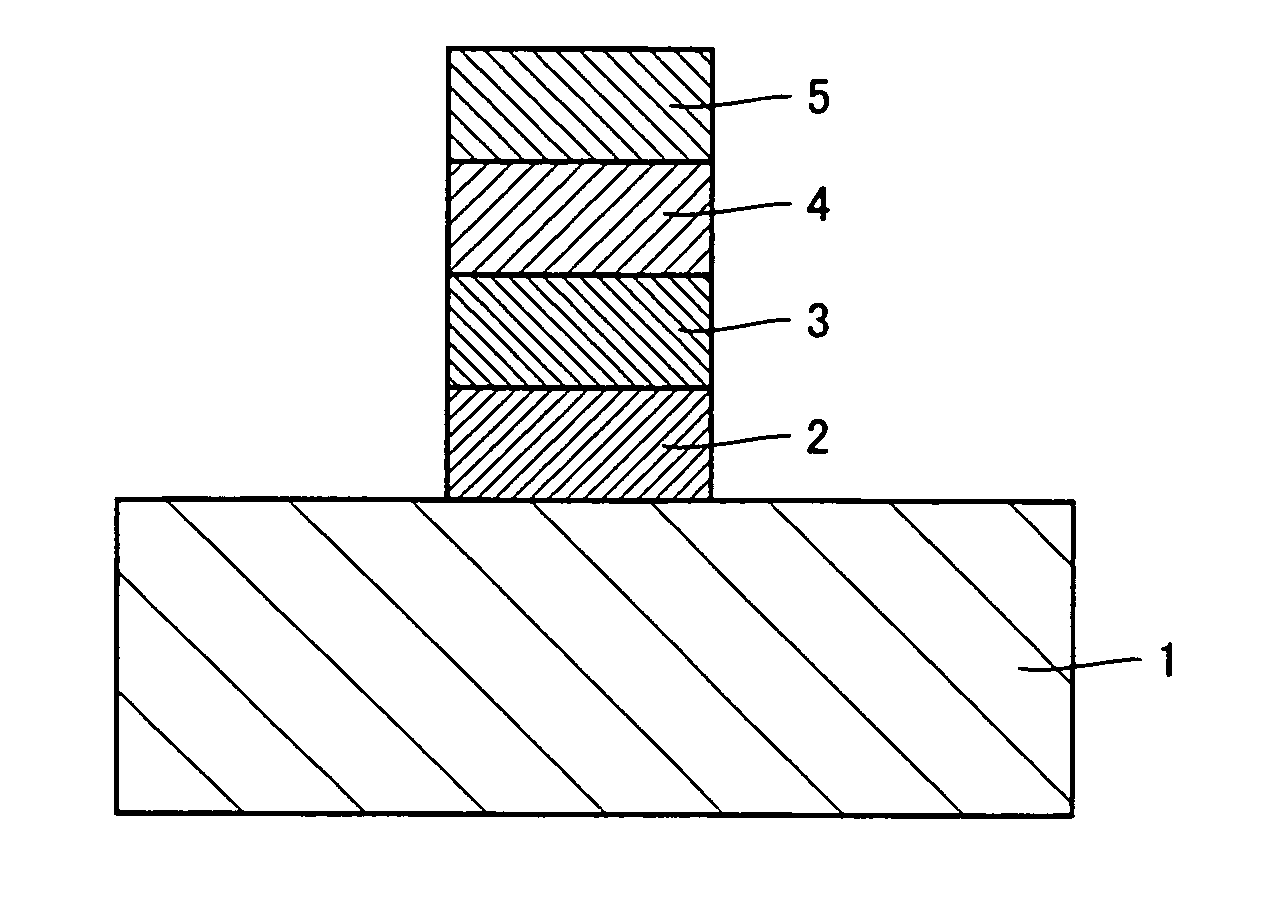
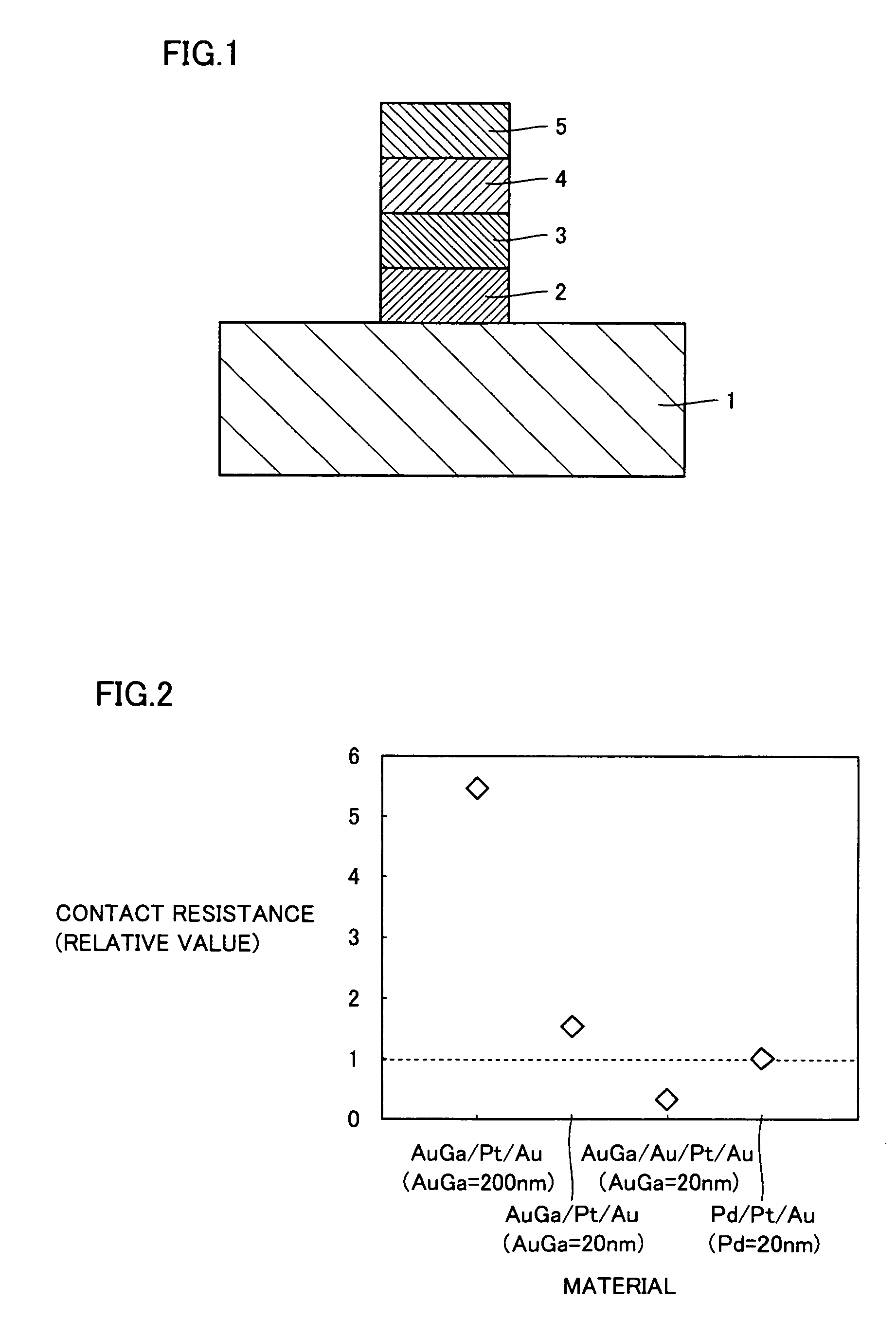
[0023]A nitride semiconductor device according to a first embodiment of the present invention is described using FIG. 1. As shown in FIG. 1, a P-type electrode is provided on a P-type contact layer 1 in the semiconductor device of this embodiment. The P-type electrode is formed with an AuGa film 2, an Au film 3, a Pt film 4, and an Au film 5. AuGa film 2 is provided on P-type contact layer 1. Au film 3 is provided on AuGa film 2. Pt film 4 is provided on Au film 3. Au film 5 is provided on Pt film 4. In the nitride semiconductor device described above, a P-type AlxGa1-xN (0≦x≦1) is used as P-type contact layer 1 which is a nitride semiconductor.

[0024]Next, a relationship between a material of a P-type electrode and a relative value of a contact resistance is described using FIG. 2. The relative value of the contact resistance of the P-type electrode indicated in FIG. 2 is a ratio to a contact resistance of a conventional P-type electrode using a Pd film. In this specification, “a re...

second embodiment

[0037]A nitride semiconductor device of a second embodiment of the present invention is described using FIG. 10. In the nitride semiconductor device of this embodiment, a P-type electrode material is provided on a top surface of P-type contact layer 1. The P-type electrode is formed with an Au film 8, an AuGa film 9, Pt film 4, and Au film 5. Au film 8 is provided on P-type contact layer 1. AuGa film 9 is provided on Au film 8. Pt film 4 is provided on AuGa film 9. Au film 5 is provided on Pt film 4.

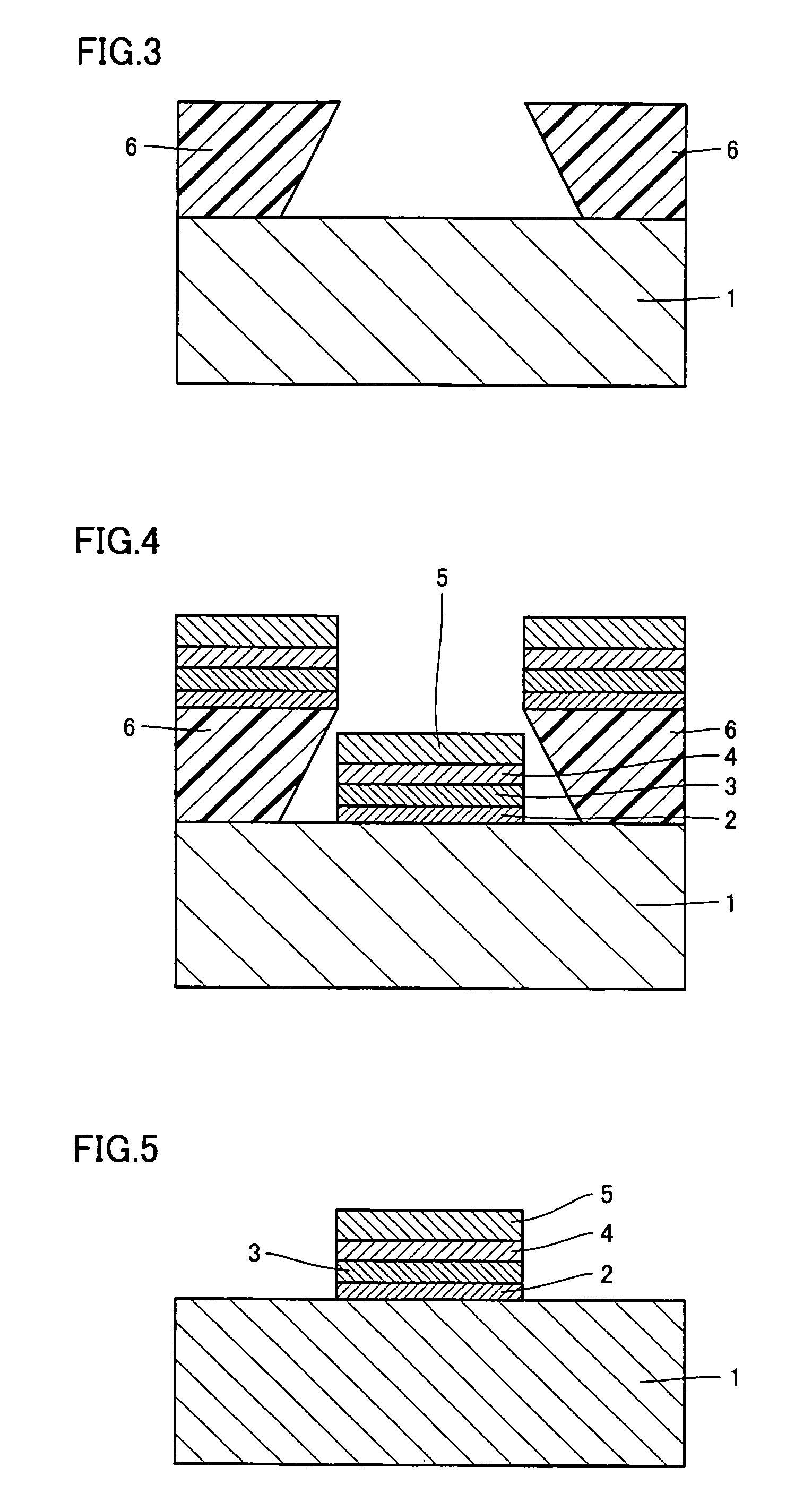
[0038]Next, a method of manufacturing the nitride semiconductor device having a structure as described above is described. The method of manufacturing is basically similar to that in the first embodiment described using FIGS. 3-5. The method of manufacturing the nitride semiconductor device of this embodiment, however, has an order of deposition of materials forming the P-type electrode different from that in the method of manufacturing the nitride semiconductor device of the first embod...


PUM

PropertyMeasurementUnit
thicknessaaaaaaaaaa
thicknessaaaaaaaaaa
temperatureaaaaaaaaaa

Abstract

A P-type electrode material is provided on a top surface of a P-type contact layer. The P-type electrode material is formed with an AuGa film, an Au film, a Pt film, and an Au film. The AuGa film is provided on the P-type contact layer. The Au film is provided on the AuGa film. The Pt film is provided on the Au film. The Au film is provided on the Pt film. With this, a nitride semiconductor device having a P-type electrode which can decrease a contact resistance between a P-type contact layer and the P-type electrode is obtained.

Description

BACKGROUND OF THE INVENTION[0001]1. Field of the Invention[0002]The present invention relates to a nitride semiconductor device including a P-type electrode and a method of manufacturing the same.[0003]2. Description of the Background Art[0004]In a conventional nitride semiconductor device, palladium (Pd) is used as a material of a P-type electrode formed on a P-type contact layer (for example, “Temperature-dependent contact resistivity of the nonalloyed ohmic contacts to p-GaN”, Joon Seop Kwak et al., JOURNAL OF APPLIED PHYSICS, VOLUME 95, NUMBER 10, May 15, 2004, PP. 5917-5919).[0005]When a laser diode, for example, is manufactured using the nitride semiconductor device as described above, if a P-type contact resistance is not sufficiently low, an operation voltage for operating the laser diode is increased and properties of the laser diode vary due to heat produced during operation. As a result, it is difficult to manufacture a laser diode which can attain stable operation and ou...

Claims


Application Information

Patent Timeline
Patent Type & Authority Patents(United States)
IPC IPC(8): H01L33/00H01L33/32H01L33/40
CPCH01L21/28575H01L33/32H01L33/40
Inventor SHIOZAWA, KATSUOMIOISHI, TOSHIYUKIKAWASAKI, KAZUSHIGEABE, YUJI
Owner MITSUBISHI ELECTRIC CORP
Why Eureka
Try Eureka