Components and testing methods for use in the production of electro-optic displays

a technology of electrooptic displays and testing methods, applied in optics, non-linear optics, instruments, etc., can solve the problems of inadequate service life of these displays, preventing their widespread use, and gas-based electrophoretic media being susceptible to the same types of problems

Inactive Publication Date: 2010-11-30
E INK CORPORATION
View PDF301 Cites 100 Cited by
  • Summary
  • Abstract
  • Description
  • Claims
  • Application Information

AI Technical Summary

Problems solved by technology

Nevertheless, problems with the long-term image quality of these displays have prevented their widespread usage.
For example, particles that make up electrophoretic displays tend to settle, resulting in inadequate service-life for these displays.
Such gas-based electrophoretic media appear to be susceptible to the same types of problems due to particle settling as liquid-based electrophoretic media, when the media are used in an orientation which permits such settling, for example in a sign where the medium is disposed in a vertical plane.
Indeed, particle settling appears to be a more serious problem in gas-based electrophoretic media than in liquid-based ones, since the lower viscosity of gaseous suspending fluids as compared with liquid ones allows more rapid settling of the electrophoretic particles.
Although many of the components used in electro-optic displays, and the methods used for their manufacture, are derived from liquid crystal displays (LCD's), the LCD assembly process (which involves flowing liquid crystal between spaced substrates) cannot be transferred to solid electro-optic displays, since the solid electro-optic medium must be secured to layers on both sides and cannot simply be slid between the two surrounding layers.
Both of these testing methods have disadvantages.
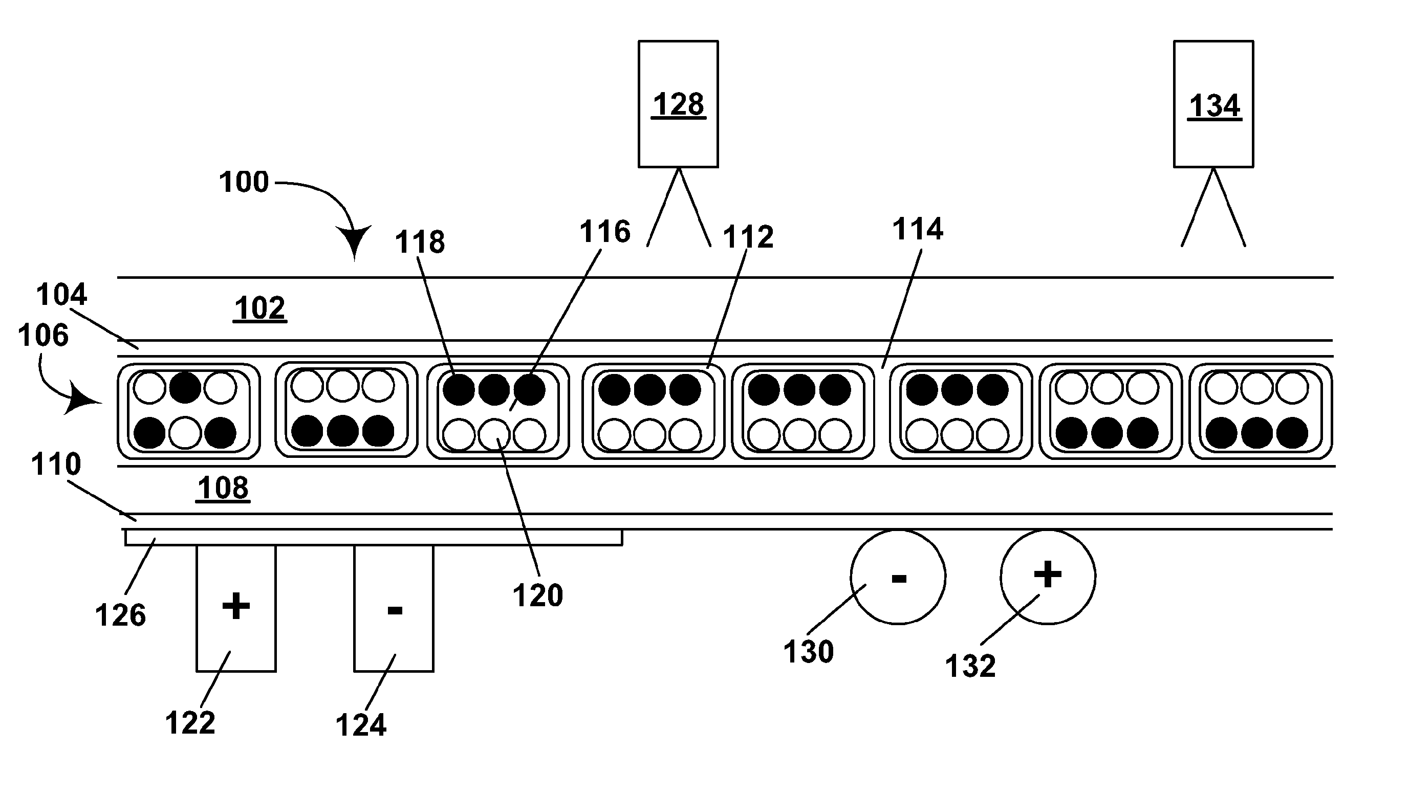
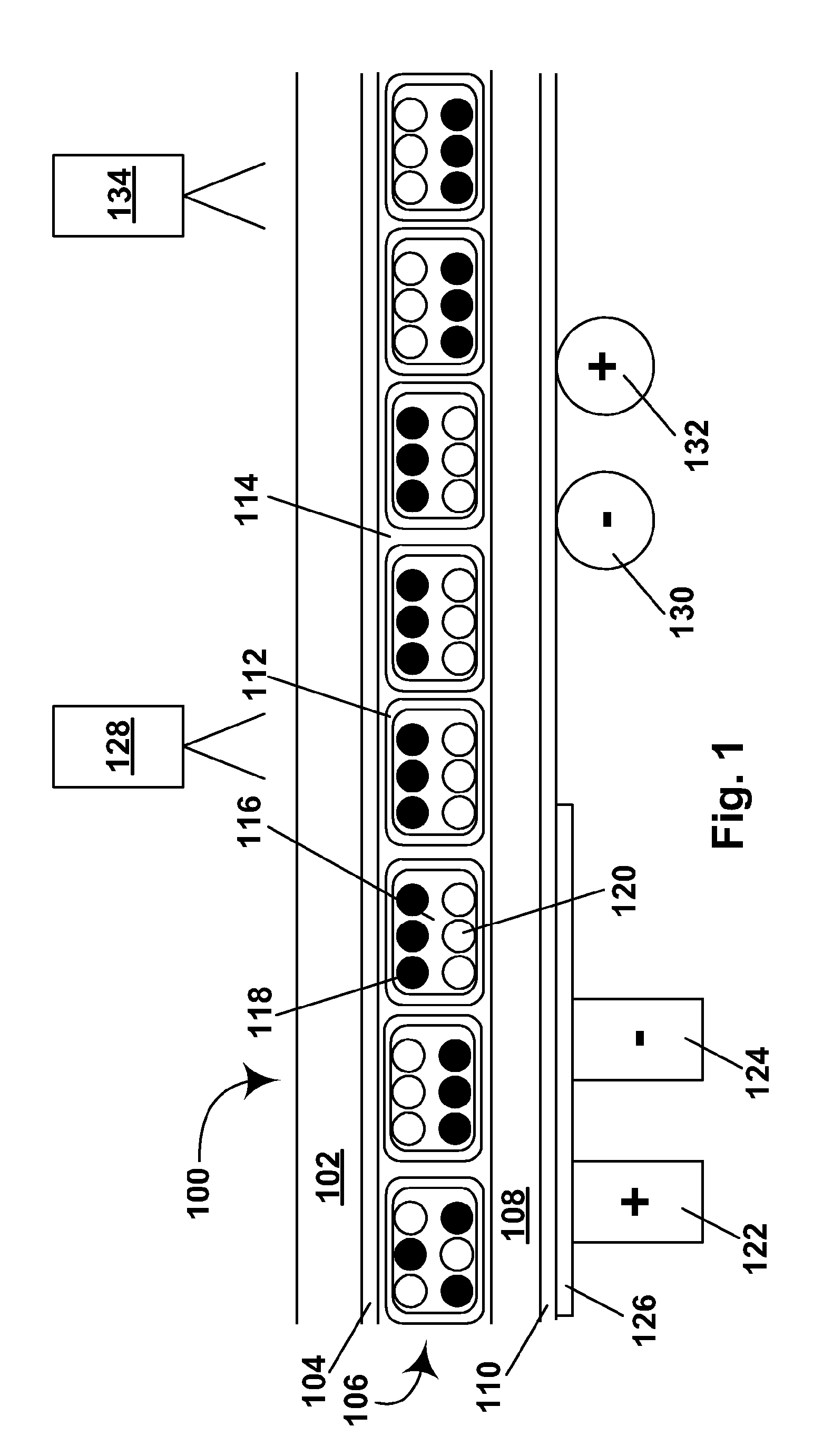
The first method requires an electrically conductive layer in the release sheet, and release sheets provided with such conductive layers are substantially more expensive than conventional release sheets which lack such conductive layers.
Furthermore, this testing method requires that electrical contact be made with the conductive layer in the release sheet, and although this can readily be done when testing is effected on an isolated piece of front plane laminate (such as the piece clamped in an electrostatic chuck illustrated in the patent—one can simply peel the release sheet away from one corner of the piece to expose the conductive layer) it may be more difficult to do if is desired to test a front plane laminate in the form of a continuous web.
In addition, the conductive layers on commercial release sheets incorporating such layers are normally opaque, so providing a release sheet with such an opaque conductive layer prevents visual inspection of one surface of the electro-optic layer in the front plane laminate during the testing.
The apparatus disclosed in the patent for effecting the second, electrostatic method, namely an ionographic print head, may also present problems.
It may be difficult to provide sufficient electrostatic charge to ensure uniform switching of the electro-optic medium if the electro-optic medium is of a type (for example, an electrochromic medium) which requires substantial current flow for switching, or if the front plane laminate is in the form of a continuous web moving at substantial speed.
The presence of certain optional layers, especially anti-static layers, on the front plane laminate may interfere with the electrostatic method.
Finally, an ionographic print head or similar electrostatic charge application device may be susceptible to edge effects which may render it difficult to ensure accurate testing of peripheral portions of a front plane laminate, especially the edges of a broad web of such material.
However, a front plane laminate does have certain limitations.
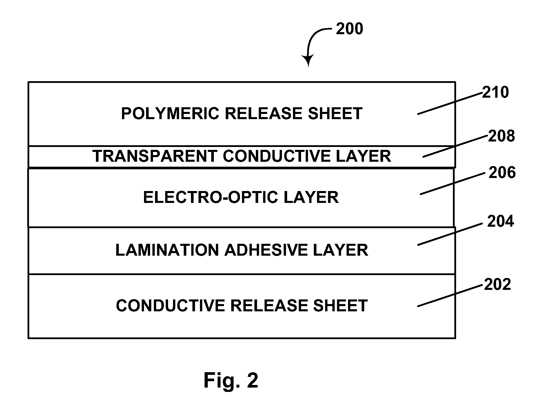
Since the FPL is normally produced by coating the electro-optic layer directly on to a substrate which will eventually form the front electrode (and typically an associated front protective layer) of the final display), the front electrode must be a coatable light-transmissive conductor, which restricts the choice of front conductor and protective layer.
For example, some possible protective layers, such as glass or thick plastic layers, may be too thick and stiff to allow coating of the electro-optic medium, while other possible substrates may be too fragile for this purpose.
Also, since practical mass production requires that the FPL be produced as a continuous web, waste occurs when portions of the web cannot be used because of the sizes and shapes of FPL pieces used to produce displays.
As the complexity and cost of the substrate to be coated increases, the cost of the substrate can substantially affect the final cost the display.
While in general the use of pre-formed contact pads tends to be more satisfactory, it does have the disadvantage of reducing flexibility in the manufacturing process; since the location of the contact pads varies with the intended application of the FPL, pre-formed contact pads fix the application in which a particular roll of FPL can be used.
It is difficult to condition an electro-optic medium derived within an FPL after the electro-optic medium has been placed between the front substrate and the lamination adhesive layer since the materials used for both the front substrate and the lamination adhesive are typically impervious to moisture, and this may lead to problems when final display assembly is conducted in poorly controlled environments.

Method used


Image

  • Components and testing methods for use in the production of electro-optic displays
  • Components and testing methods for use in the production of electro-optic displays
  • Components and testing methods for use in the production of electro-optic displays

Examples


Embodiment Construction

[0049]As already indicated, in one aspect this invention provides a method for testing a laminate comprising a layer of a solid electro-optic medium having two extreme optical states, and an electrically conductive layer. The method comprises passing the laminate over a pair of electrodes maintained at different potentials, the laminate being passed over the electrodes such that during this passage the electrically conductive layer lies on the opposed side of the layer of electro-optic medium from the electrodes. The potential difference between the pair of electrodes is maintained large enough to switch the electro-optic medium substantially to one of its extreme optical states. After passage past the electrodes, the switched electro-optic medium can be inspected visually (a term which is used herein to include machine vision) to detect defective areas.

[0050]In a preferred form of this method, after being passed over the (first) pair of electrodes, the laminate is passed over a sec...


PUM

PropertyMeasurementUnit
diameteraaaaaaaaaa
thicknessaaaaaaaaaa
thicknessaaaaaaaaaa

Abstract

A laminate comprising a solid electro-optic medium and an electrically conductive layer is tested by passing it over a pair of electrodes at different potentials, with the electrically conductive layer lying on the opposed side of the electro-optic medium from the electrodes. An article which can be tested by this method, and which is useful in the manufacture of electro-optic displays, comprises a layer of a solid electro-optic medium and a release sheet comprising an electrically conductive layer.

Description

REFERENCE TO RELATED APPLICATIONS[0001]This application claims benefit of Application Ser. No. 60 / 597,279, filed Nov. 21, 2005, and of Application Ser. No. 60 / 744,022, filed Mar. 31, 2006.[0002]This application is also a continuation-in-part of application Ser. No. 10 / 605,024, filed Sep. 2, 2003 now U.S. Pat. No. 7,561,324, (Publication No. 2004 / 0155857), which claims benefit of Application Ser. No. 60 / 319,516, filed Sep. 3, 2002. This application is also a continuation-in-part of application Ser. No. 10 / 907,065, filed Mar. 18, 2005 (Publication No. 2005 / 0146774, now U.S. Pat. No. 7,236,292), which is a divisional of application Ser. No. 10 / 249,957, filed May 22, 2003 (now U.S. Pat. No. 6,982,178), which claims benefit of Application Ser. No. 60 / 319,300, filed Jun. 10, 2002, and of Application Ser. No. 60 / 320,186, filed May 12, 2003.[0003]This application is related to:[0004](a) application Ser. No. 10 / 904,063, filed Oct. 21, 2004 (now U.S. Pat. No. 7,110,164), which is a continuati...

Claims


Application Information

Patent Timeline
Patent Type & Authority Patents(United States)
IPC IPC(8): G02F1/03G02F1/167
CPCG02F1/1309G02F1/167G02F1/1334G02F1/133514G02F2001/133354G02F1/133354
Inventor DANNER, GUY M.ZALESKY, JONATHAN L.RITTER, JOHN E.O'MALLEY, TIMOTHY J.WHITESIDES, THOMAS H.PATRY, SHAMUS FORDBOUCHARD, ALAINWEBBER, RICHARD M.
Owner E INK CORPORATION
Why Eureka
Try Eureka