Method of circulating while retrieving downhole tool in casing

a technology of casing and tool, which is applied in the direction of drilling casings, drilling pipes, borehole/well accessories, etc., can solve the problems of casing becoming stuck in the well, requiring special equipment, and reverse circulation damage to the open hole formation

Active Publication Date: 2010-12-07
SCHLUMBERGER TECH CORP
View PDF15 Cites 5 Cited by
  • Summary
  • Abstract
  • Description
  • Claims
  • Application Information

AI Technical Summary

Benefits of technology

[0009]In another embodiment, the circulation tool has an inner pipe with a lower threaded end that connects to the drill pipe and an upper threaded end that connects to the top drive. An outer housing surrounds the inner pipe, defining an annular chamber between the inner pipe and the outer housing. The outer housing is threaded on its lower end so as to connect to the landing sub. The bottom of the annular chamber is open and in fluid communication with the inner annulus between the drill pipe and the casing. A side port allows the operator to pump fluid into the annular chamber and down the inner annulus of the casing.

Problems solved by technology

While successful, this technique requires special equipment not always found on a drilling rig, such as a wireline winch and sheaves to guide and lower the wireline into the casing.
However, some operators fear that reverse circulation will damage the open hole formation.
A possibility exists that the casing may become stuck in the well while the drill pipe is tripped in and out.
This can particularly be a problem if the operator plans to drill deeper with the string of casing.
Also, reciprocating the casing up and down reduces the chances of it becoming stuck.
Another issue while retrieving and re-running a bottom hole assembly is to provide a safety barrier in the event that a formation begins to flow liquid or gas, referred to as a “kick” while the drill pipe is located inside the casing.
However, no arrangement presently exists that allows circulation through the casing while a string of drill pipe is being run in or retrieved inside casing.

Method used


Image

  • Method of circulating while retrieving downhole tool in casing
  • Method of circulating while retrieving downhole tool in casing
  • Method of circulating while retrieving downhole tool in casing

Examples


Embodiment Construction

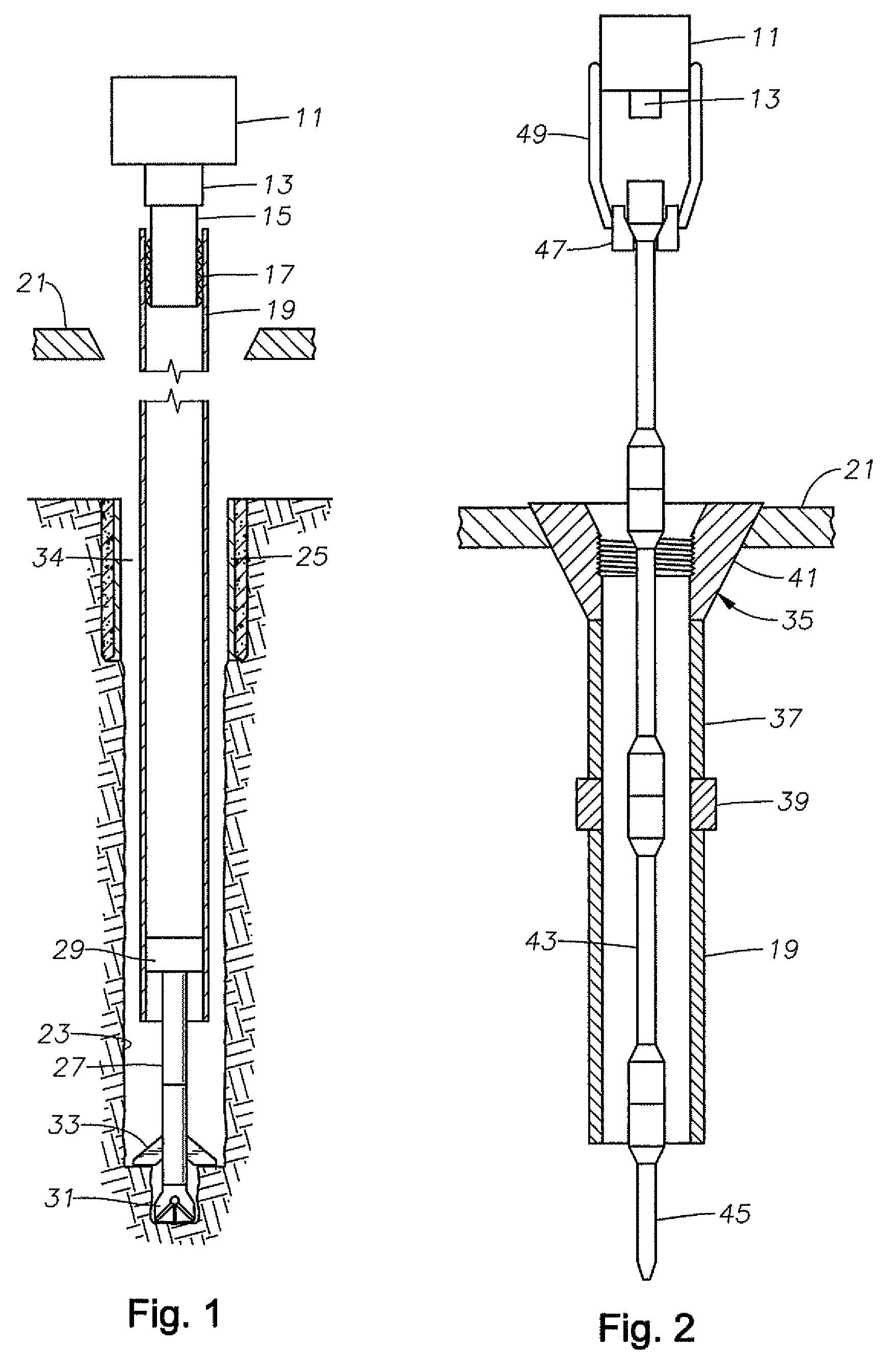
[0020]Referring to FIG. 1, top drive 11 is a conventional top drive of a drilling rig that moves up and down a derrick (not shown). Top drive 11 has a drive quill 13 that it rotates. A casing gripper 15 is mounted to drive quill 13 during a casing-while-drilling operation. Casing gripper 15 has slips 17 on a lower portion that are moved radially by an actuator to grip casing 19. In this embodiment, slips 17 are moved outward to grip the inner diameter of casing 19. Alternatively, the slips of casing gripper 15 could be arranged to fit around the casing and move inward to grip the exterior of casing 19.

[0021]Casing 19 is a string of conduit made up of sections of pipe secured together by couplings or casing collars. Casing 19 is eventually cemented in a wellbore to line the wellbore. Normally casing 19 extends from the bottom to the top of the wellbore where it is secured to a wellhead assembly (not shown). The term “casing” is also meant to include other tubular strings cemented in ...


PUM


Abstract

Retrieving a down hole tool at a lower end of a string of casing can be performed with drill pipe during a casing-while-drilling operation. The operator suspends the casing in the well from a drilling rig floor opening. A string drill pipe is lowered into the casing while the casing is suspended for engaging and retrieving the down hole tool. When circulation is desired, the operator secures a circulation tool to an upper end of the drill pipe, then lowers the drill pipe and the circulation tool to close off an upper end of an inner annulus between the drill pipe and the casing. The operator circulates fluid down the circulation tool and the drill pipe and back up an outer annulus surrounding the casing. The connection between the circulation tool and the casing allows the operator to reciprocate the casing.

Description

FIELD OF THE INVENTION[0001]This invention relates in general to casing wells while drilling and in particular to circulating and reciprocating the casing while retrieving the bottom hole assembly with drill pipe.BACKGROUND OF THE INVENTION[0002]Most oil and gas wells are drilled using drill pipe. After a certain depth is reached, the operator runs a string of casing into the open borehole and cements the casing in place. The operator may then run drill pipe into the casing to drill below the casing to a greater depth. In a casing-while-drilling technique, all or a portion of the well is drilled using the casing as the drill string. The operator mounts a bottom hole assembly to the lower end of the casing. The bottom hole assembly includes a drill bit and a reamer. The operator may rotate the casing, which in turn rotates the drill bit to drill the well. The operator may also employ a mud motor that rotates the drill bit relative to the casing in response to drilling mud pumped down...

Claims


Application Information

Patent Timeline
Patent Type & Authority Patents(United States)
IPC IPC(8): E21B23/00
CPCE21B7/20E21B33/068E21B23/00E21B23/01
Inventor WARREN, TOMMY M.HONEYCUTT, PRESTON T.BROUSE, MICHAEL
Owner SCHLUMBERGER TECH CORP
Why Eureka
Try Eureka