Oil pump

a technology of oil pump and pulsating chamber, which is applied in the direction of machines/engines, liquid fuel engines, positive displacement liquid engines, etc., can solve the problems of difficult to achieve the absorption of pulsation due to the dynamic pressure in the discharge port, the amplitude (pulsation) of the discharge pressure change, and the noise increase, so as to achieve better absorption, improve the absorption effect of the chamber and the function of the chamber with respect to the pulsation characteristics

Active Publication Date: 2010-12-07
HONDA MOTOR CO LTD +2
View PDF13 Cites 0 Cited by
  • Summary
  • Abstract
  • Description
  • Claims
  • Application Information

AI Technical Summary

Benefits of technology

[0013]It is an object of the present invention to be able to adequately absorb the pulsation due to the dynamic pressure of the oil flow in the discharge flow channel so as to facilitate a reduction in pulsation and a reduction in unwanted effects on other devices, and a reduction in noise and so on.
[0021]Accordingly, the introduction path effectively introduces pulsation due to dynamic pressure of the oil flowing along the discharge flow channel into the chamber whereupon, as a result, vibration can be absorbed. As a result, an adequate reduction of hydraulic pulse of the oil that flows into the flow channel that communicates with the discharge flow channel can be achieved, and the effects on the devices to which the oil is supplied and through which it is circulated, and the noise and so on, can be reduced.
[0022]In the invention, by adoption of an oil pump in which an introduction path is formed in the same direction as the flow direction of the discharge flow channel, pulsation due to the dynamic pressure of the oil in the discharge flow channel can be even more effectively introduced into the chamber and, accordingly, o can be even better absorbed. In the invention, by formation of an introduction path narrower than the discharge flow channel, pulsation can be even better absorbed. More particularly, by matching the size of the introduction path to pulsation characteristics of the oil, the absorption effect of the chamber can be further improved and the function of the chamber with respect to the pulsation characteristics can be more adequately demonstrated.
[0024]In the invention as a result of the chamber being formed in plurality and the plurality of chambers being formed in series, the chamber volume can be enlarged and a better effect can be achieved. In the invention as a result of the plurality of chambers being each of a different volume, the chambers of respectively different volume are able to deal with the different pulsation frequencies of the various pulsations of varying frequencies (vibration) and, accordingly, the pulsation can be absorbed.
[0025]Next, in the invention, as result of the communication between the flow channel and the discharge flow channel at approximately right angles in the configuration described above, the introduction path and chambers can be easily arranged in a position front on to the flow direction of the oil and the structure of the pump can be simply and efficiently configured.
[0027]Furthermore, by forming the flow channel, which communicates in a direction at right angles with the discharge flow channel, into a circular-shaped hole, with the interior of this flow channel serving as the circumferential inside surface, flow of the oil in which the pulsation has been adequately reduced can be more uniformly stabilized and, in addition, flow resistance can be reduced. This circular-shaped hole can be easily formed using a rotary tool or the like.

Problems solved by technology

As a result, pressure is generated in the oil that flows to the discharge port and a pulsing of the oil being propelled out occurs resulting in changes in the amplitude (pulsation) of the discharge pressure.
The dynamic pressure, which constitutes the main cause of the pulsation, creates load on the devices and pipe members and so on through which oil from the oil pump is supplied and, in addition, as a result of the resonance thereof, leads to increased noise.
Absorption of pulsation due to dynamic pressure in the discharge port is hard to achieve in the oil chamber of Japanese Patent Application Laid-open No. 2005-146998 described above because direct introduction of the dynamic pressure in the flow direction of the oil into the oil chamber is difficult.
However, as the dynamic pressure is generated along the flow direction of the oil and the introduction thereof into the oil chamber in a direction other than the flow direction is difficult, in reality an essentially negligible reduction is achieved.
Accordingly, absorption of the dynamic pressure of pulsation is difficult in an oil chamber that communicates at right angles with respect to the flow direction of the oil in the flow channel of the discharge port and, as a result, achieving an adequate pulsation reduction is difficult.
Consequently, in conventional oil chambers an adequate effect in terms of reducing the pulsation due to dynamic pressure cannot be achieved, and reduction of the unwanted effects on other devices, and reduction of noise and so on, is difficult.

Method used


Image

  • Oil pump
  • Oil pump
  • Oil pump

Examples


Embodiment Construction

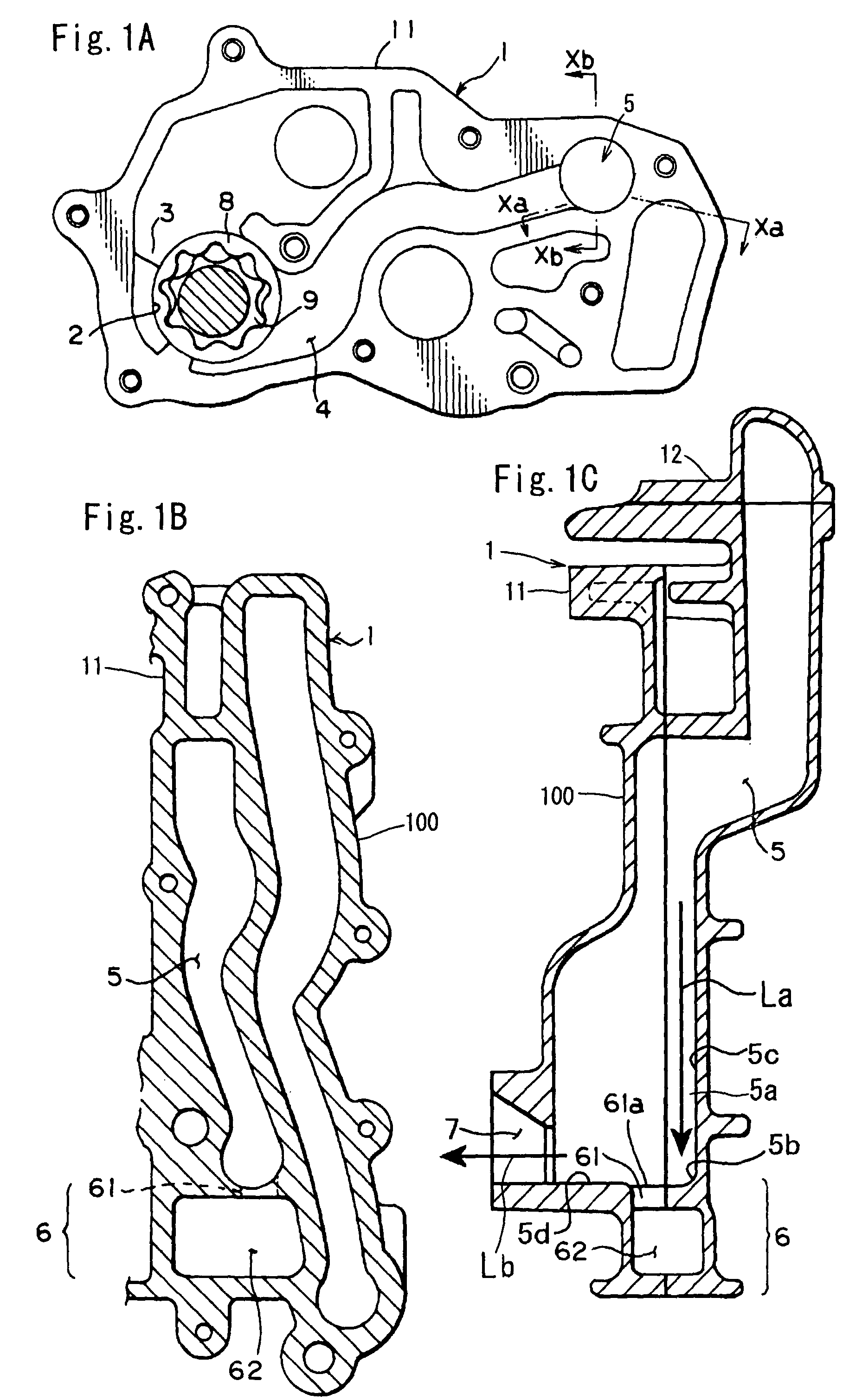
[0035]An embodiment of the present invention will be hereinafter described with reference to the diagrams. First, in the present invention, a pump casing 1 is configured from two pump bodies 11, 12 and joined by a fastening means such as a bolt and nut. As shown in FIG. 6, the pump casing 1 is integrally formed with a casing of a balancer folder 100. As shown in FIG. 1A, a rotor chamber 2, a suction port 3 and a discharge port 4 are formed in the interior of the pump casing 1.

[0036]A rotor is arranged in the rotor chamber 2. More specifically, the rotor is configured from a non-contacting type gear mechanism comprising two gear rotors. Hereinafter the present invention taken to be based on a torocoid pump in which the rotor is configured from a torocoid-toothed outer rotor 8 and inner rotor 9.

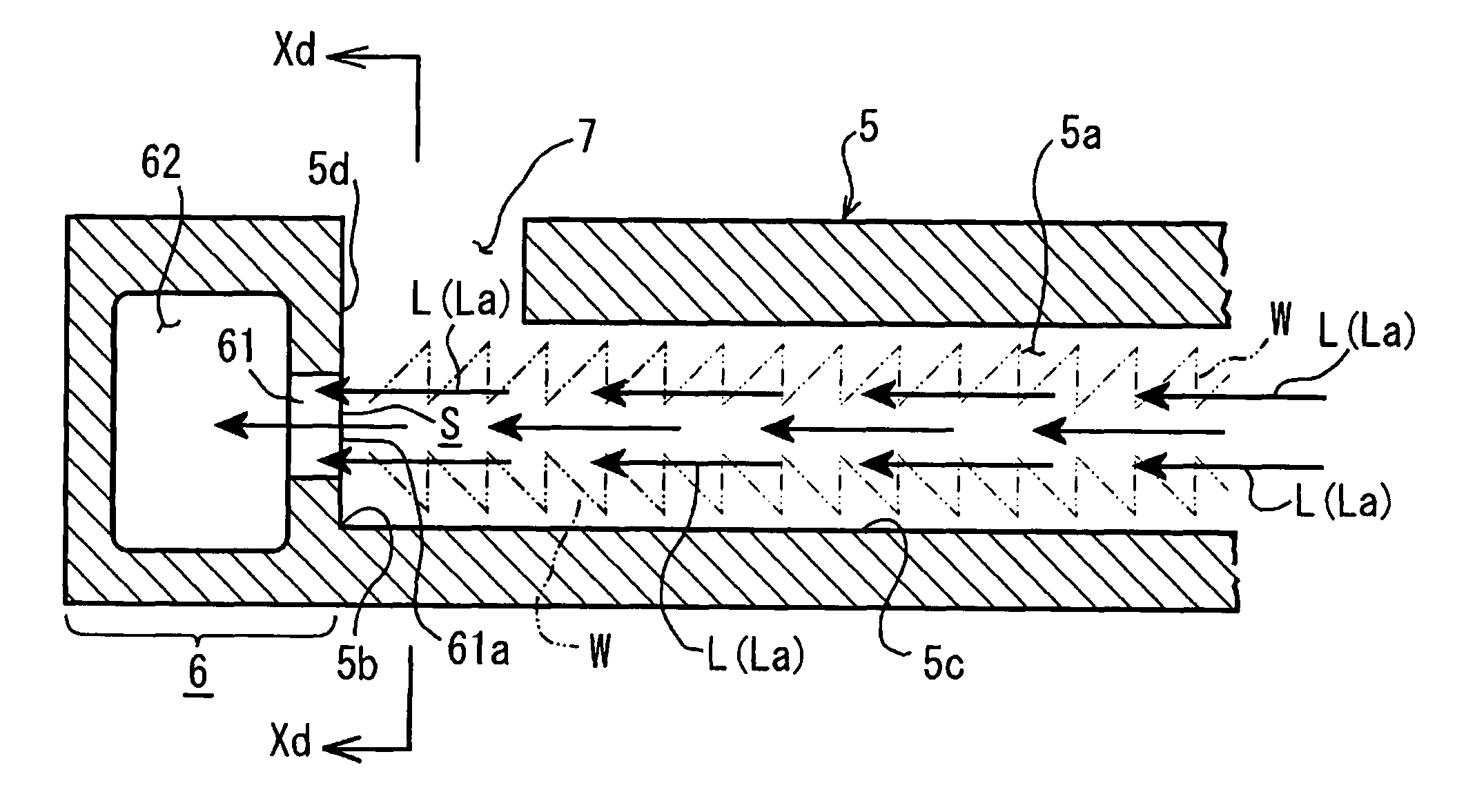
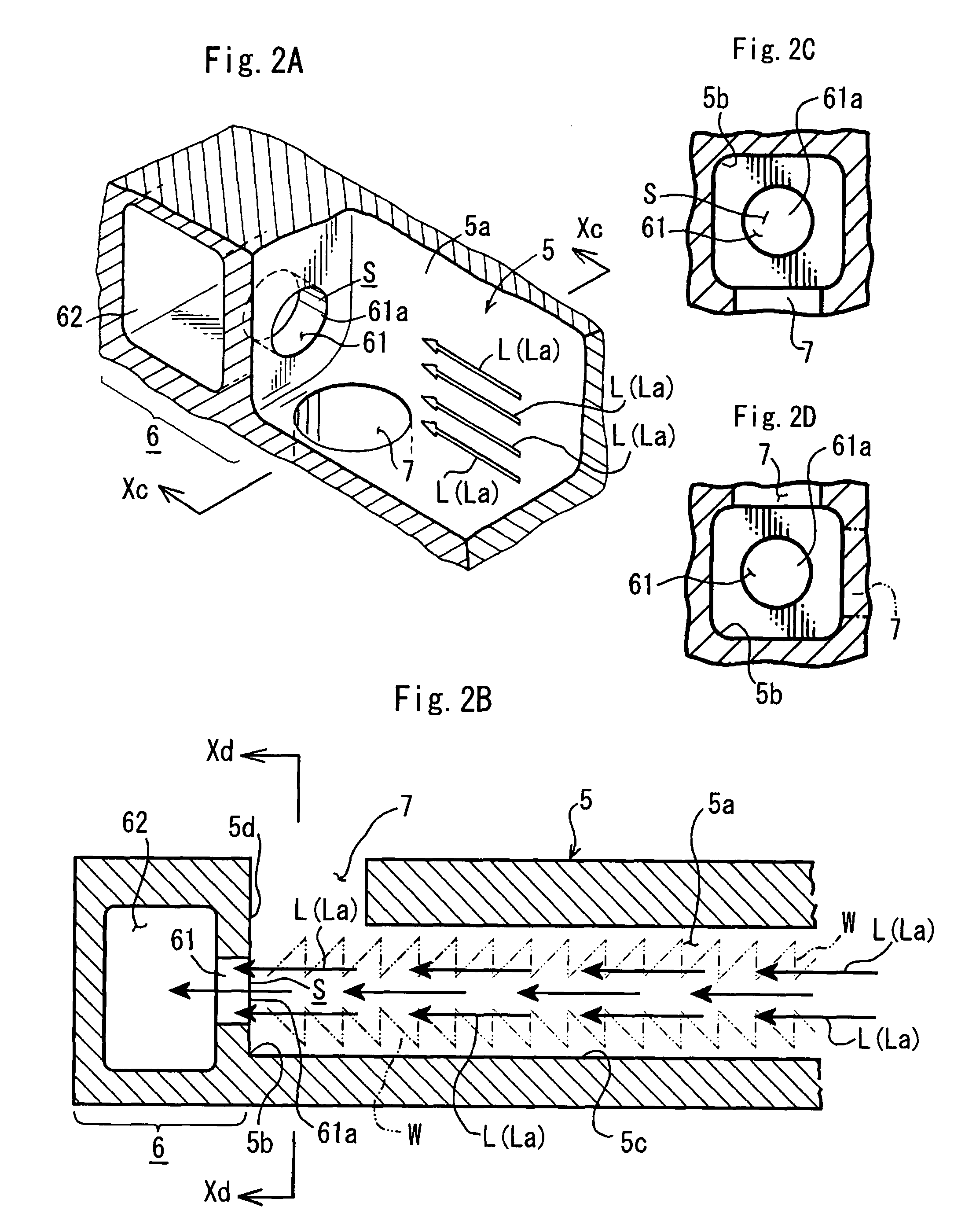
[0037]As shown in FIG. 1A, a discharge flow channel 5 is communicatingly formed with the discharge port 4. The discharge port 4 is formed to cross the interior of the pump casing 1, and the dis...


PUM


Abstract

An oil pump in which pulsation vibration due to the dynamic pressure on the discharge port side can be attenuated. In an oil pump for transporting fluid from a suction port to a discharge port by the rotation of a rotor mounted in a pump casing, a resonator configured from an introduction path and a chamber is formed with respect to a discharge flow channel that communicates with the discharge port in the flow direction of the discharge flow channel. A channel in a direction different to the flow direction of the discharge flow channel is communicatingly formed in the vicinity of the resonator.

Description

BACKGROUND OF THE INVENTION[0001]1. Field of the Invention[0002]The present invention relates to an oil pump in which pulsation vibration due to dynamic pressure on the discharge port side can be attenuated.[0003]2. Description of the Related Art[0004]Japanese Patent Application Laid-open No. 2005-146998 discloses an oil pump comprising a torocoid-toothed or similar rotor for attenuating the vibration and so on due to pulsation on the discharge port side thereof. Japanese Patent Application Laid-open No. 2005-146998 discloses the provision in a part of the discharge port of a throttle of reduced cross-sectional area. The application also discloses the provision in the vicinity of the discharge port in the downstream side thereof of an oil chamber that communicates with the discharge port by way of the throttle.[0005]The oil chamber communicates with the discharge port by way of a narrow communication hole that communicates in the vertical direction with a flow channel of the dischar...

Claims


Application Information

Patent Timeline
Patent Type & Authority Patents(United States)
IPC IPC(8): F03C2/00F04B11/00
CPCF04C15/0049F04C2/10F04C2210/14
Inventor KONDO, TAKASHIISO, KAZUHIKOKOIWA, YOJIROONO, YASUNORIYANAGISAWA, ATSUSHIKANEKO, ATSUSHI
Owner HONDA MOTOR CO LTD
Why Eureka
Try Eureka