Method for the manufacture of a molding as well as a sensor unit for the application thereof

a sensor unit and manufacturing method technology, applied in the direction of additive manufacturing processes, ventilation systems, heating types, etc., can solve the problems of affecting the measurement accuracy of the sensor unit, the levelling assembly colliding with the build platform or the base plate, and the layer not being sufficiently secure to the base plate, etc., to achieve the effect of reducing the cost, simple conditions for adjusting the starting position, and increasing the measurement certainty

Active Publication Date: 2010-12-07
TRUMPF WERKZEUGMASCHINEN GMBH & CO KG
View PDF8 Cites 71 Cited by
  • Summary
  • Abstract
  • Description
  • Claims
  • Application Information

AI Technical Summary

Benefits of technology

[0007]The method according to the invention facilitates exact adjustment of the thickness of the first powder layer, irrespective of the heating temperature of the build platform and / or the base plate attached thereupon in a detachable manner as well as of the thermal expansions resulting therefrom in the build platform or base plate and the adjacent components. The adjustment of a starting position of the build platform for application of the first powder layer is achieved via an intermediate position which is defined for the powder layer to be applied by a sensor assembly in an indirect or direct manner. After the intermediate position has been detected by the sensor assembly, a drive subsequently lowers the build platform in relation to the sensor assembly by a distance corresponding to the thickness of the first powder layer, resulting in an exact adjustment of the starting position of the build platform for application of the first powder layer. Thereby, it is possible to eliminate any thermal elongations.
[0022]According to a further advantageous embodiment of the sensor unit, it is provided that the levelling assembly comprises at least a length which exceeds a dimension of the build platform or of the base plate extending in transverse direction in relation to the travel direction of the levelling assembly and that the at least one sensor element comprises a length which is equal to or less than the dimension of the build platform or of the base plate extending in transverse direction in relation to the travel direction of the levelling assembly. As a result, the sensor assembly can exactly detect the position of contact between the sensor assembly that is designed as a strip of brushes and the build platform or the base plate. Over and above this, this embodiment is advantageous in that, for example while prefabricated moldings are being treated, exact detection of the intermediate position of the build platform is enabled irrespective of their geometry and extension in the plane of the build platform or the base plate.

Problems solved by technology

If the first powder layer applied is too thick, there is the risk that the layer fails to comprise a sufficiently secure connection to the base plate.
If the powder layer applied is too thin, this might result in height errors which may be continued while further layers are being built.
If the levelling assembly is a rigid one, such as a slide or a grinding shaft, there is the risk that the levelling assembly collides with the build platform or the base plate if the powder layer is too thin.
The presently manual adjustment of the build platform for achieving an exact thickness of the first powder layer is difficult in that the build platform is preheated to temperatures in excess of 250 degrees C., in order to prevent internal stresses from developing while the molding is being built.
Where generative methods such as selective laser melting are utilized, the build platform is heated to temperatures of up to 500 degrees C; in exceptional cases, there might even be higher temperatures of up to 600 degrees C. This heating process causes considerable thermal expansions which also affect the position of the build platform.
This complicates the adjustment of an exact thickness of the first powder layer for the manufacture of a molding.

Method used


Image

  • Method for the manufacture of a molding as well as a sensor unit for the application thereof
  • Method for the manufacture of a molding as well as a sensor unit for the application thereof
  • Method for the manufacture of a molding as well as a sensor unit for the application thereof

Examples


Embodiment Construction

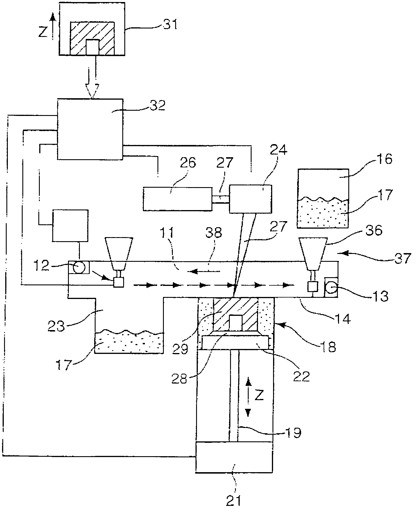
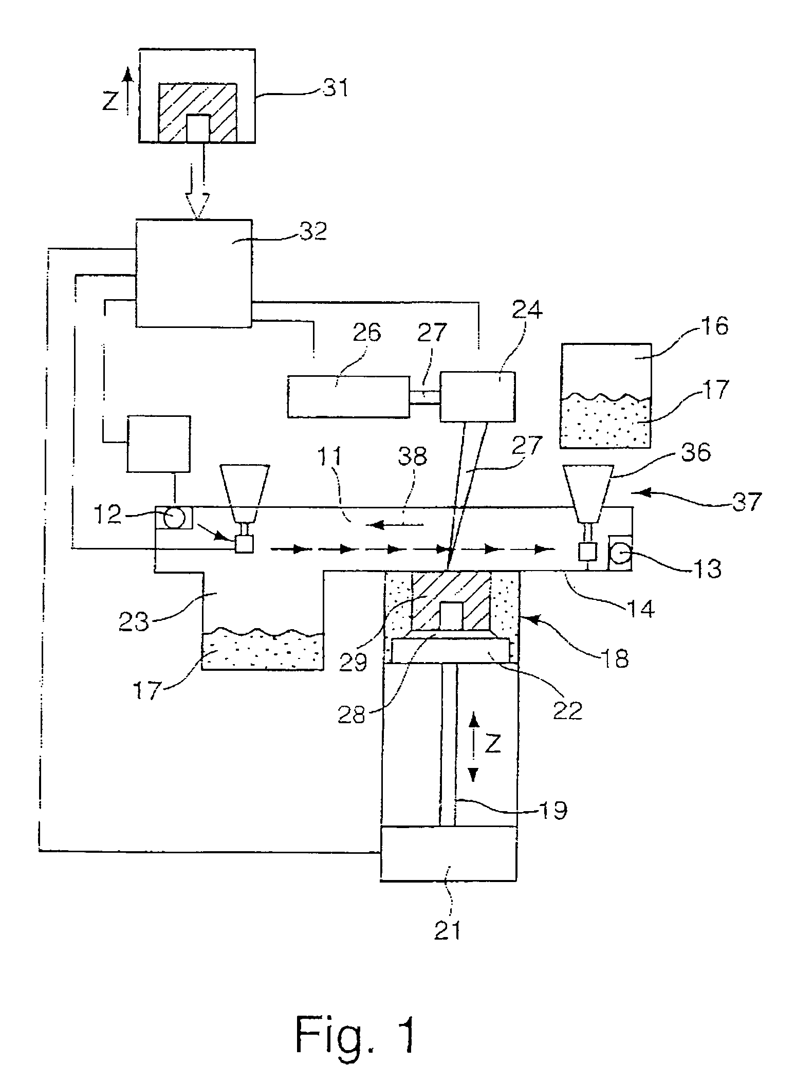
[0031]FIG. 1 shows an apparatus for selective laser melting, such as it is, for example, described in DE 198 53 978 C1. Said apparatus comprises a process chamber 11 with a protective gas inlet 12 and a protective gas outlet 13. A storage tank 16 that is filled with material powder 17 is provided above a bottom area 14. For example, the powder used may be steel, titanium or aluminum. A build chamber 18 ends in the bottom area 14 from below, wherein a build platform 22 driven by a drive 21 via a lifting screw 19 is arranged in said build chamber 18. A base plate 28 is arranged on the build platform 22 in a detachable manner. A collection tank 23 for the material powder 17 is provided next to the build chamber 18. A displacement assembly 24 directing a laser beam 27 generated by a laser 26 onto the build platform 22 or base plate 28 is provided above the build chamber 18.

[0032]In order to produce a molding 29, for example a prototype of a component, the component coordinates are, in a...


PUM

PropertyMeasurementUnit
thicknessaaaaaaaaaa
thicknessaaaaaaaaaa
electric resistanceaaaaaaaaaa

Abstract

The invention relates to a method for the manufacture of a molding through generative processing methods, in particular through selective laser melting, wherein a model of a molding is built from a powder material according to CAD data, wherein an application unit is used to apply a powder layer and the powder layer applied is fixed to a layer arranged there under or a base plate by means of radiation, characterized in that prior to applying a first layer onto a build platform or a base plate, a sensor assembly having a sensor level which is located in relation to the levelling level of a levelling assembly for the applied powder layer is allocated to the build platform or the base plate, the build platform or the base plate is moved in relation to the sensor assembly until the sensor assembly emits a signal for stopping the build platform to a drive in an intermediate position, and starting from the intermediate position, the build platform or the base plate is moved by a distance to adjust the layer thickness of the first powder layer and is positioned in a starting position.

Description

BACKGROUND OF THE INVENTION[0001]The invention relates to a method for the manufacture of a molding, in particular through selective laser melting, according to the pre-characterizing clause of Claim 1, and to a sensor unit, in particular for application of the method.[0002]The present invention refers to a technology known as “rapid prototyping”. Such methods are preferrably used in product development, in order to reduce the product development time and to increase the product quality. In addition, this method allows manufacture of complex geometric shapes directly from a three-dimensional CAD model. For example, such a method has been disclosed in DE 196 49 865 C1.[0003]The material powder is distributed over the build platform or the build space by means of a levelling assembly, for example through a linear movement of a slide levelling the material powder to the layer thickness desired. Whenever a layer has been treated with the laser beam, the levelling assembly distributes ne...

Claims


Application Information

Patent Timeline
Patent Type & Authority Patents(United States)
IPC IPC(8): B23K26/00B29C35/08
CPCB22F3/003B22F3/1055B29C67/0077B22F2998/00B22F2203/03B22F2003/1056B29C64/153B33Y10/00B33Y30/00Y02P10/25B22F10/28B22F12/60B22F10/37B22F12/90
Inventor RENZ, BERNDBAUER, JOHANNESBRAUN, STEFANWELLER, NICOLE
Owner TRUMPF WERKZEUGMASCHINEN GMBH & CO KG
Why Eureka
Try Eureka