Heatsink with periodically patterned baseplate structure

a heatsink and periodic pattern technology, applied in the field of heatsinks, can solve the problems of heatsinks being particularly problematic, degrading or limiting the effective performance of circuits, and adding cost to printed circuit board assemblies, so as to reduce electromagnetic noise propagation

Active Publication Date: 2010-12-07
LENOVO GLOBAL TECH INT LTD
View PDF7 Cites 25 Cited by
  • Summary
  • Abstract
  • Description
  • Claims
  • Application Information

AI Technical Summary

Benefits of technology

[0009]A third embodiment is a method of reducing the propagation of electromagnetic noise generated by a microprocessor. A frequency band of the electromagnetic noise generated by the microprocessor is identified. A periodic pattern of spaced apart patches interconnected by branches is selected, with geometry having stopband within the identified frequency band. The processor is thermally contacted with a heatsink having a base that includes an electrically-conductive, thermally-conductive material having the selected periodic pattern.

Problems solved by technology

Electromagnetic interference (EMI) is a disturbance that affects an electrical circuit due to electromagnetic radiation.
The disturbance may interrupt, obstruct, or otherwise degrade or limit the effective performance of the circuit.
Undesirable electromagnetic radiation often originates in integrated circuits (ICs), and is radiated by other structures at a level sufficient to cause interference with other components.
A heatsink can be particularly problematic.
Heatsink grounding schemes exist that attempt to address the problem, but these workarounds add cost to a printed circuit board assembly and also consume a substantial portion of the limited space on a circuit board.

Method used


Image

  • Heatsink with periodically patterned baseplate structure
  • Heatsink with periodically patterned baseplate structure
  • Heatsink with periodically patterned baseplate structure

Examples


Embodiment Construction

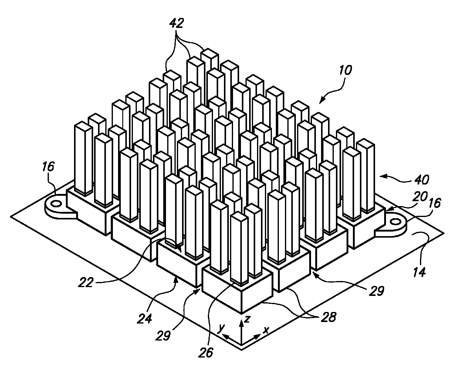
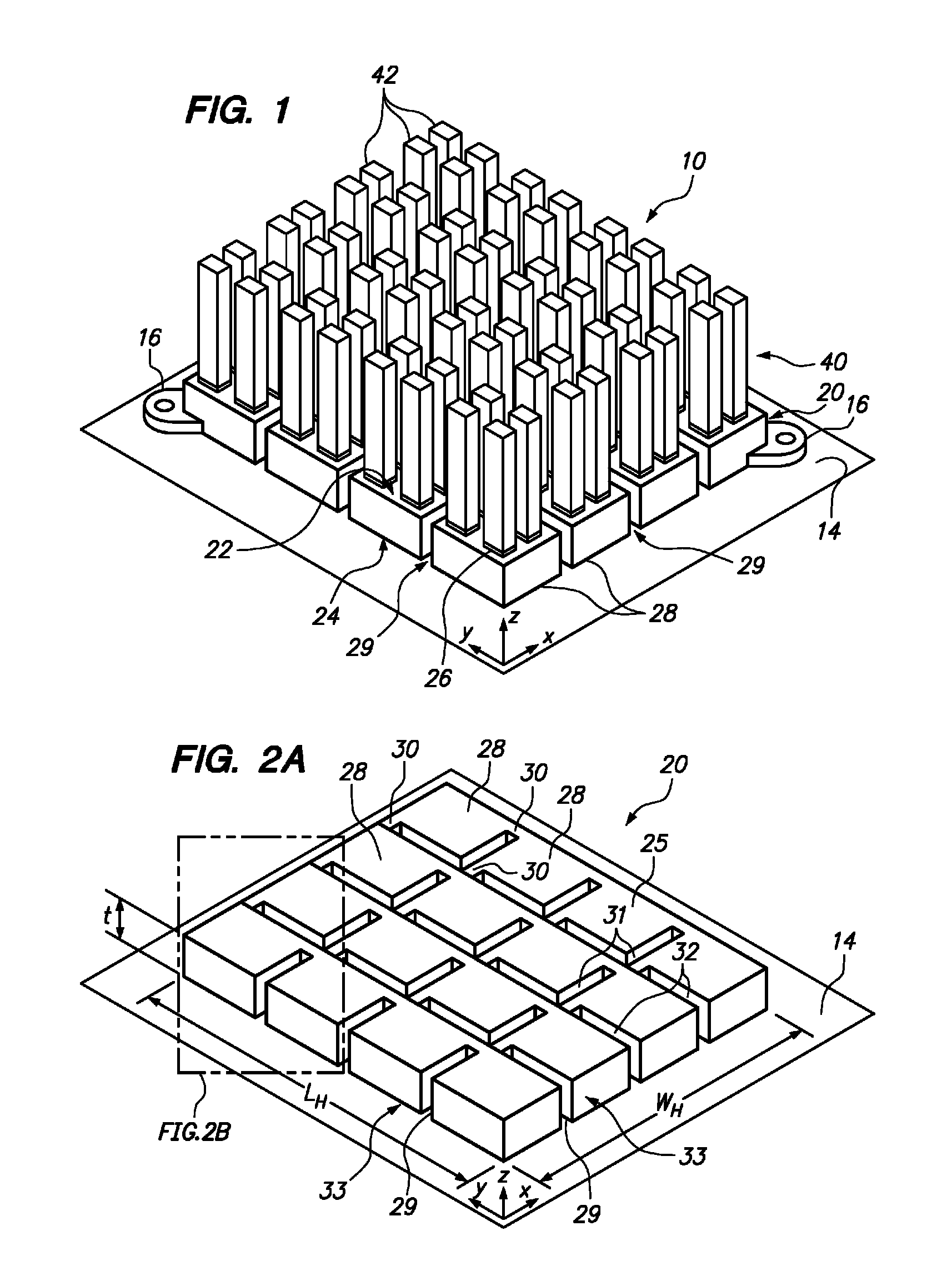
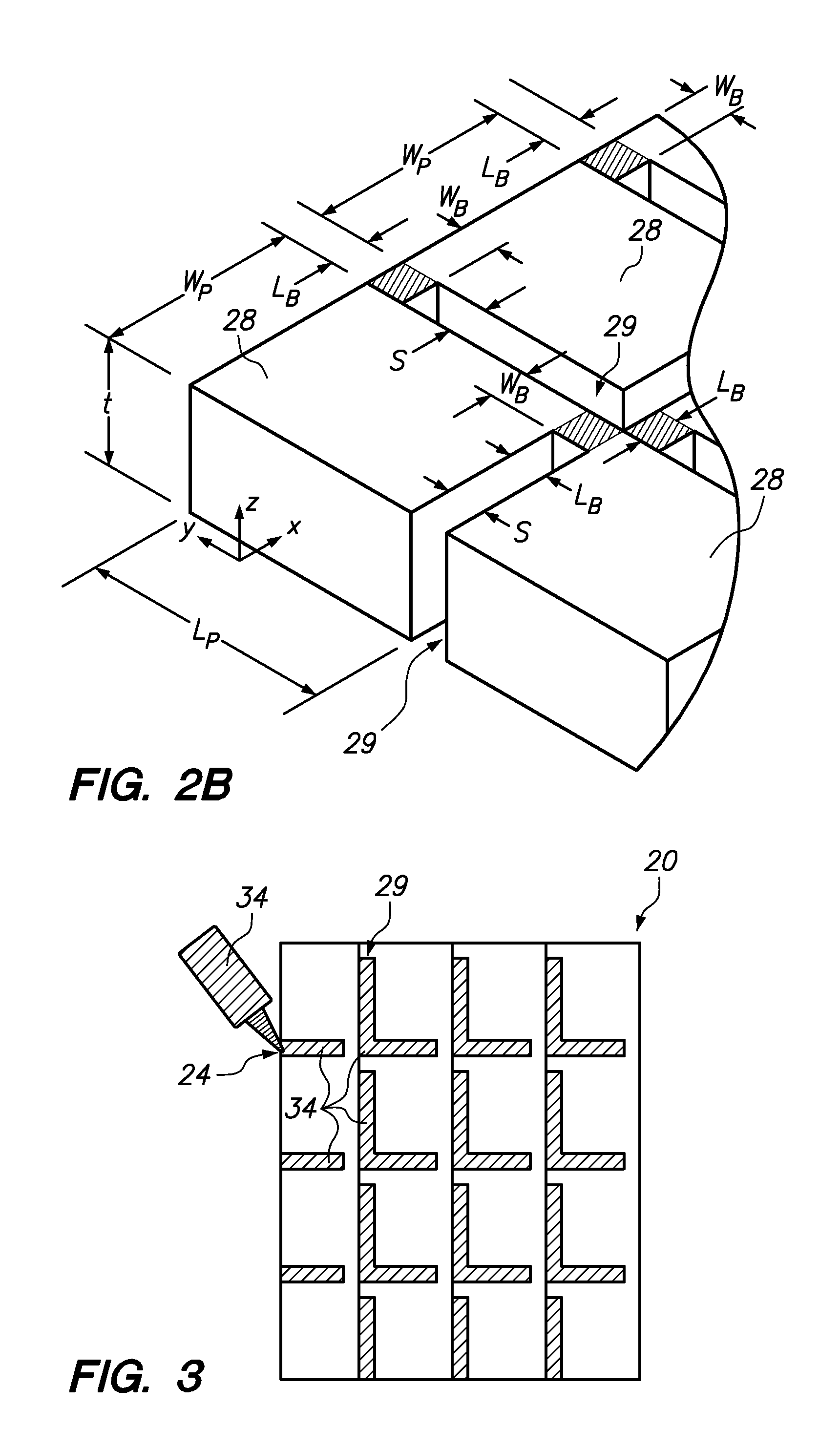
[0020]Embodiments of the invention are directed to reducing electromagnetic interference (EMI) caused by an integrated circuit (IC) in an electronic device. One embodiment is a heatsink for an IC incorporating a periodically patterned structure within the base of the heatsink. The periodically patterned structure, together with a solid metal layer of a circuit board (e.g. ground layer or power layer), form an electromagnetic bandgap (EBG) structure that reduces the efficiency of the heatsink acting as an antenna in certain frequency bands. The periodically patterned structure includes a periodic array of electrically-conductive patches interconnected by electrically-conductive branches. Openings in the periodically-patterned structure are filled with a thermally-conductive but electrically non-conductive filler, which maximizes heat transfer within the heatsink without undermining the electrical properties of the EBG structure. Heatsink fins are coupled to the heatsink base using a ...


PUM


Abstract

A heatsink including an electromagnetic bandgap structure reduces electromagnetic interference caused by an integrated circuit in an electronic device. One embodiment provides a heatsink having a base with an array of electrically-conductive, thermally-conductive patches spaced apart in two dimensions of a reference plane and having a thickness perpendicular to the reference plane. The patches are interconnected by a plurality of branches. Each branch connects adjacent patches and has a width in the reference plane of less than a width of each adjacent patch. A plurality of thermally conductive cooling fins coupled to a surface of the base and extend normal to the reference plane. The cooling fins may be formed of a thermally-conductive, electrically non-conductive material or may be coupled to the base by a thermally-conductive, electrically non-conductive material. The periodically patterned structure of the base, together with a solid metal layer of a circuit board, form an electromagnetic bandgap structure that reduces certain frequencies of electromagnetic noise caused by the integrated circuit.

Description

BACKGROUND OF THE INVENTION[0001]1. Field of the Invention[0002]The present invention relates to reducing the propagation of electromagnetic interference, particularly in the context of heatsinks for integrated circuits.[0003]2. Background of the Related Art[0004]Electromagnetic interference (EMI) is a disturbance that affects an electrical circuit due to electromagnetic radiation. The disturbance may interrupt, obstruct, or otherwise degrade or limit the effective performance of the circuit. Undesirable electromagnetic radiation often originates in integrated circuits (ICs), and is radiated by other structures at a level sufficient to cause interference with other components. A heatsink can be particularly problematic. Due to its large, metallic surface area, a heatsink may serve as an efficient antenna for propagating electromagnetic radiation.[0005]Numerous approaches to reducing EMI are known in the art. One approach to reducing EMI is the use of bypass or “decoupling” capacitor...

Claims


Application Information

Patent Timeline
Patent Type & Authority Patents(United States)
IPC IPC(8): H05K7/20
CPCH01L23/3677H01L23/467H01L23/552H01L2924/0002H01L2924/00
Inventor ARCHAMBEAULT, BRUCE R.CHIKANDO, ERIC N.CONNOR, SAMUEL R.MAAS, JOHN S.
Owner LENOVO GLOBAL TECH INT LTD
Why Eureka
Try Eureka