Bifold transport lock

a technology of transport lock and bifold, which is applied in the direction of adjusting device, soil-working method, agricultural tools and machines, etc., can solve the problems of rake arms that can open unexpectedly, lock mechanism failure, and heavy and cumbersome both in operation and in transport, so as to reduce the number of ropes, chains, other mechanical operating means, and reduce the possibility of damage to the arms or hydraulic system

Active Publication Date: 2010-12-14
KUHN NORTH AMERICA
View PDF19 Cites 27 Cited by
  • Summary
  • Abstract
  • Description
  • Claims
  • Application Information

AI Technical Summary

Benefits of technology

[0013]In one example of the invention, the operator does not need to leave the tractor cab to lock or unlock the arms when changing between the transport and operating positions of the machine. Therefore, the operator does not need to remember to pin (lock) or unpin (unlock) the transport mechanism before or after transport, and the possibility of damage to the arms or hydraulic system is reduced. Another potential advantage is that there is less chance of accidental opening of rake arms due to hydraulic failure or operator error or omission.
[0014]Additionally, the number of ropes, chains, other mechanical operating means can be reduced inasmuch as the system may be configured to operate automatically upon actuation of the same cylinder or cylinders that move the arms themselves.

Problems solved by technology

These long rake arms, of which there are two in so-called “bifold” rakes, can be heavy and cumbersome both in operation and in transport.
This method relies on the integrity of the hydraulic system, and the rake arms can open unexpectedly upon a failure of the cylinder, hoses, or valve.
In other words, if hydraulic pressure is lost, the locking mechanism may fail.
Serious damage can be caused if the operator forgets to remove the pins before trying to hydraulically operate the rake arms.
This method can be difficult inasmuch as the holes in the pipe may not line up with the holes in the rake arms, and the operator is required to force the pipe into position.

Method used


Image

  • Bifold transport lock
  • Bifold transport lock
  • Bifold transport lock

Examples


Embodiment Construction

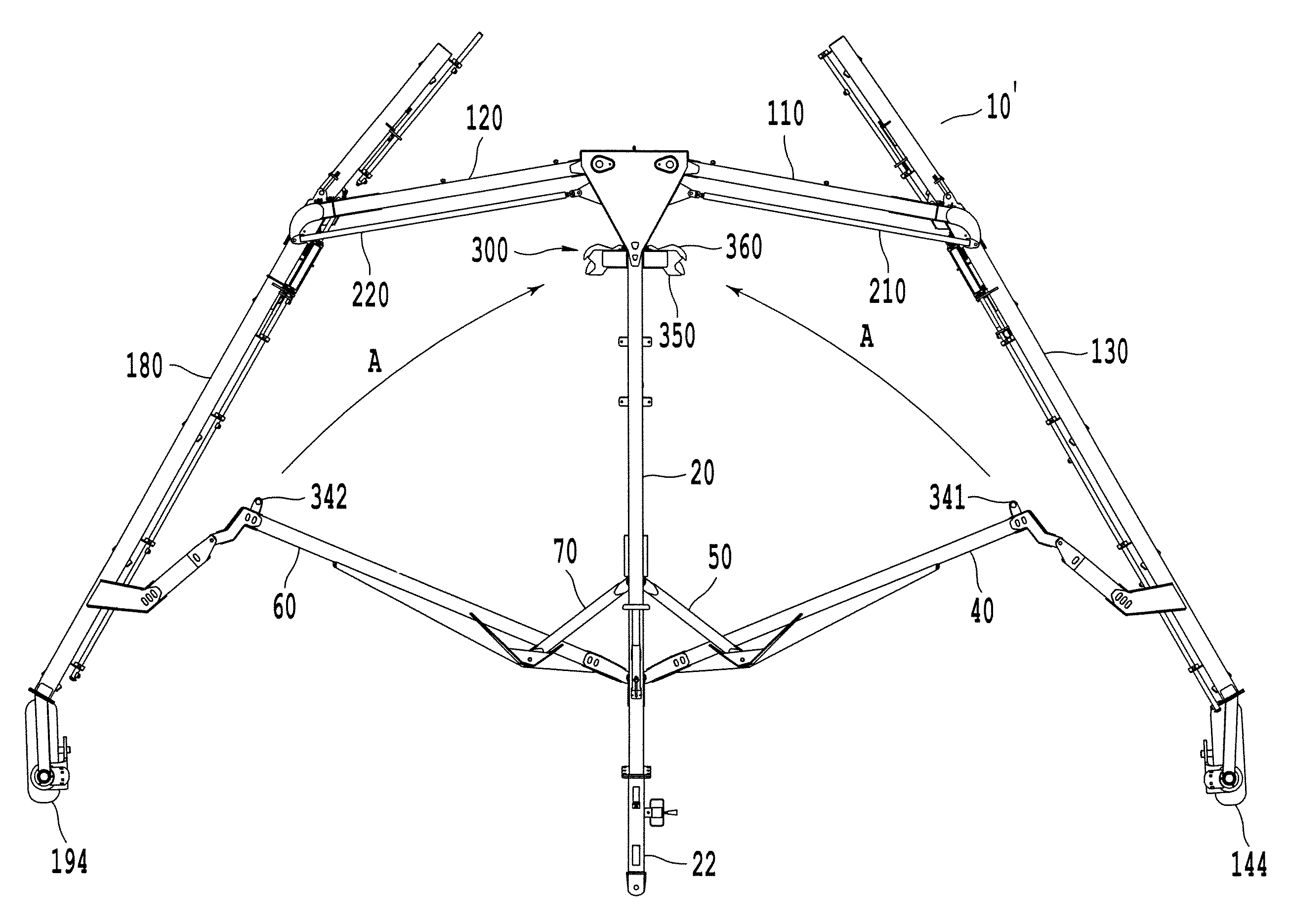
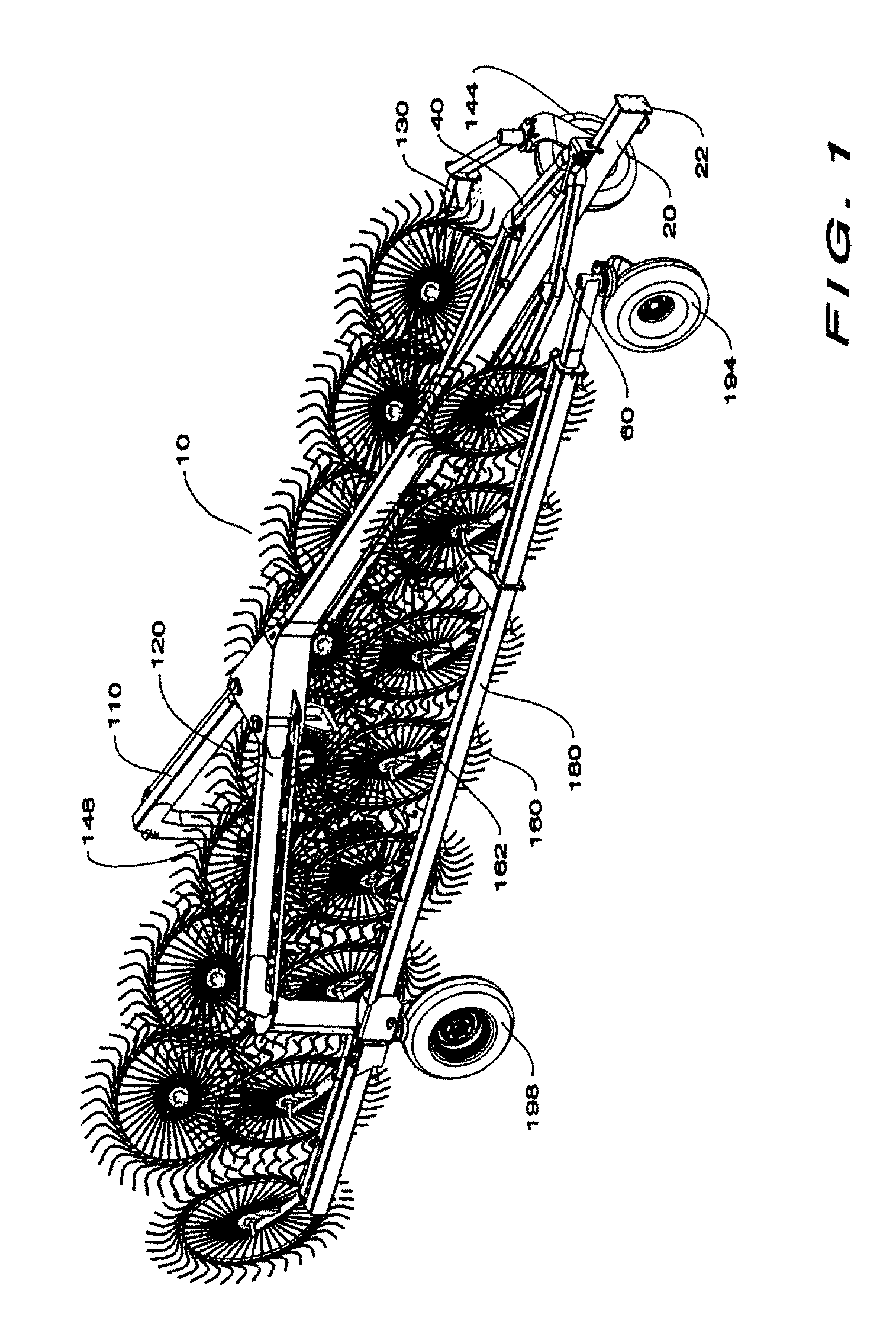
[0036]With reference to FIG. 1, one non-limiting embodiment of a rake apparatus is generally designated by the reference number 10. FIG. 8 shows a similar rake apparatus 10′, but with a specialized locking device 300 included.

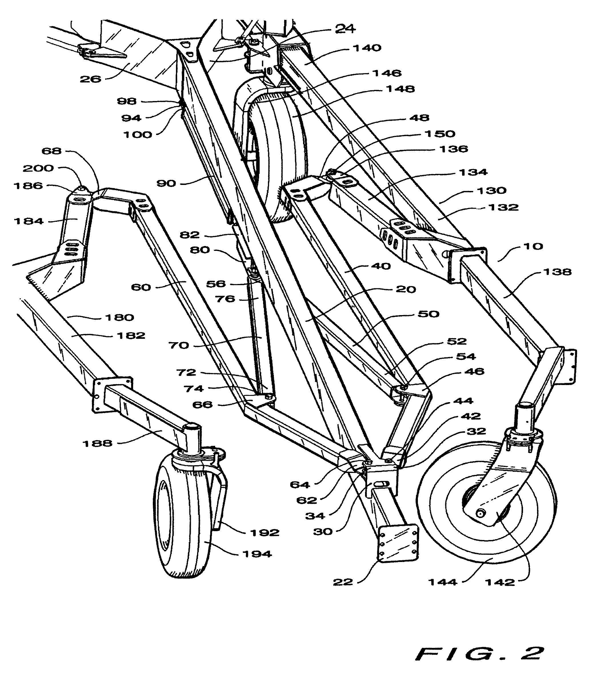
[0037]The rake apparatus 10 includes a tongue assembly 20, which includes a hitch 22 at a forward end (note that the hitch need not be connected at the very end of the tongue assembly, but can be positioned somewhat toward the middle). The rake apparatus is configured to be pulled forward by connection with the hitch 22. As viewed facing forward, toward the direction of travel, a left rake arm assembly 130 and a right rake arm assembly 180 each include a plurality of tined rake wheels 160 attached to the rake arm assemblies 130 and 180 by a plurality of rake wheel arms 162. The left rake arm assembly 130 also includes rake arm wheels 144 and 148, and the right rake arm assembly 180 includes rake arm wheels 194 and 198. The rake arm assemblies 130 and 180 are at...


PUM


Abstract

An apparatus includes a tongue, a pivotable beam linked to the tongue, a cylinder configured to move the pivotable beam from an operating position to a transport position, which is narrower than the operating position, and a latchable member connected to the pivotable beam. A locking assembly includes first and second dogs which can receive the latchable member. The second dog can move relative to the first dog from an open position to a closed position in response to movement of the latchable member such that movement of the latchable member out of the second dog opening is blocked by the first dog while the second dog is in the closed position. The apparatus includes a locking member that moves in response to movement of the cylinder from an unlocked to a locked position to lock the dogs in the closed position.

Description

BACKGROUND OF THE INVENTION[0001]1. Field of the Invention[0002]This invention relates to an agricultural rake device. In one example, the invention relates to a locking device for a bifold or V-rake type. In an exemplary embodiment, the bifold rake is used for raking grass or hay.[0003]2. Description of the Related Art[0004]Agricultural rakes are used to form windrows from cut crops, such as, for example, hay, straw, corn fodder, and grasses. It is a typical agricultural process to cut these crops, rake or merge them into windrows where additional drying may occur, collect and store the crops, and subsequently feed the crops to livestock.[0005]Modern power equipment for raking cut forage employs rotating tined wheels and particularly banks of rotating tined wheels that are moved through a field of cut forage to form windrows. These banks of wheel rakes can be quite wide to reduce both the time and number of passes required to rake a field. Because of the wide widths employed by rak...

Claims


Application Information

Patent Timeline
Patent Type & Authority Patents(United States)
IPC IPC(8): A01B49/00
CPCA01B73/067A01D78/1014A01D78/146
Inventor MARGGI, JEFF
Owner KUHN NORTH AMERICA
Why Eureka
Try Eureka